本节主要刷一些常见的面试手撕题,做一个简单记录。
计数器相关
1.从慢时钟域到快时钟域的计数采样start脉冲信号
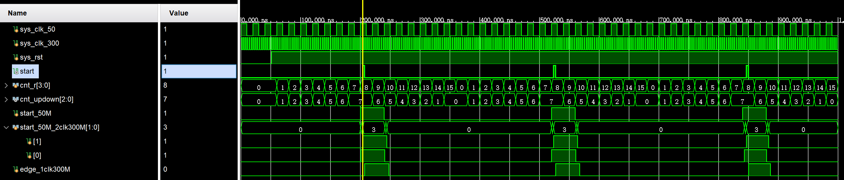
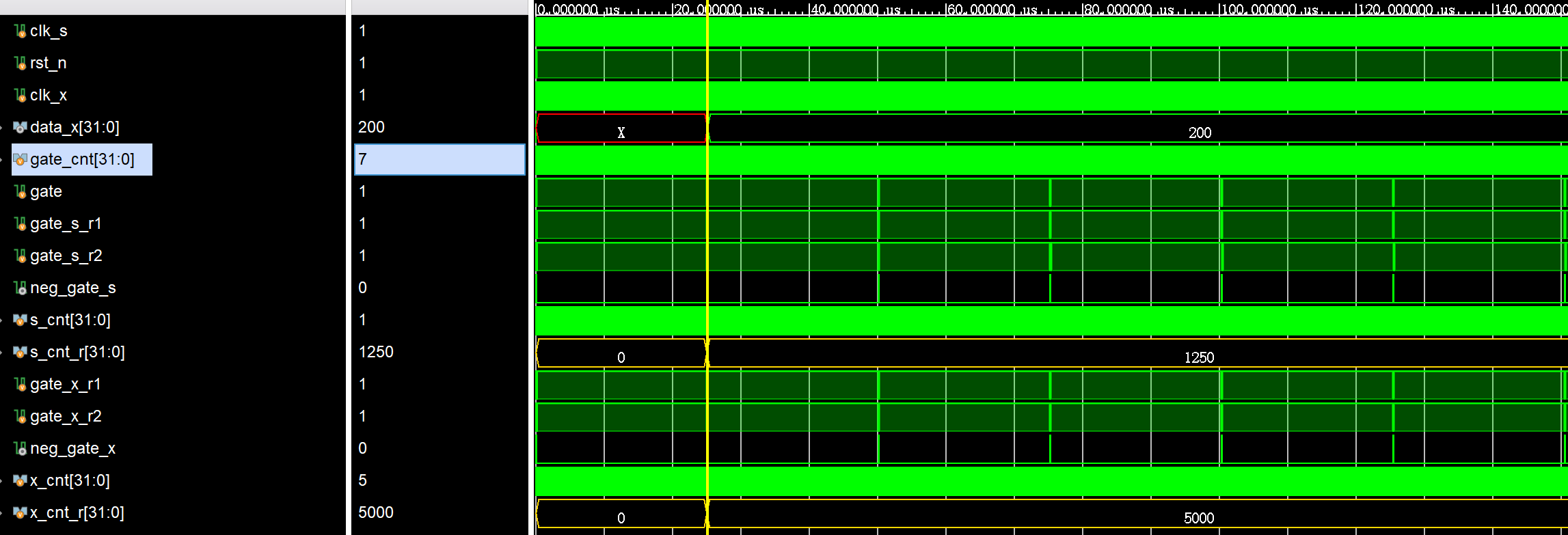
CLK1时钟域(50MHz)有一个3bit的二进制计数器CounterA,从0计数到7,再从7计数到0,计数步长为1;CLK2时钟域(300MHz)采样到计数器为CounterA出现了一次7的时候,产生一个单周期(CLK2周期)的脉冲start,请设计一个合理的方案。
分析:50MHz—>300MHz采样start信号时,不能只打两拍,这样不能产生单周期(CLK2周期)的脉冲start,而是需要再通过一级上升沿检测得到clk2周期的start信号
写法:下面代码中利用cnt_r扩展1bit以实现从0到7递增,再从7到0递减有点意思
1
2
3
4
5
6
7
8
9
10
11
12
13
14
15
16
17
18
19
20
21
22
23
24
25
26
27
28
29
30
31
32
33
34
35
36
37
38
39
40
41
42
43
44
45
46
47
48
49
50
51
52
53
54
55
56
57
58
59
60
61
62
63
64
65
66
67
module CNT_start_slow2fast(
input sys_clk_50 ,
input sys_clk_300 ,
input sys_rst ,
output start
);
reg [3 : 0] cnt_r;
wire [2 : 0] cnt_updown; //利用cnt_r扩展1bit以实现从0到7递增,再从7到0递减
reg start_50M;
reg [1 : 0] start_50M_2clk300M;
reg edge_1clk300M;
//50M时钟域下计数
always @(posedge sys_clk_50 or negedge sys_rst) begin
if(~sys_rst) begin
cnt_r <= 'd0;
end
else begin
cnt_r <= cnt_r + 1'd1;
end
end
//根据cnt_r实现cnt_updown的递增递减
assign cnt_updown = cnt_r[3] ? ~cnt_r[2 : 0]: cnt_r[2 : 0];
//在50M时钟域下生成start信号
always @(posedge sys_clk_50 or negedge sys_rst) begin
if(~sys_rst) begin
start_50M <= 'd0;
end
else begin
if(&cnt_updown) begin
start_50M <= 'd1;
end
else begin
start_50M <= 'd0;
end
end
end
//在300M时钟域下同步start_50M信号,即寄存两拍
always @(posedge sys_clk_300 or negedge sys_rst) begin
if(~sys_rst) begin
start_50M_2clk300M <= 'd0;
end
else begin
start_50M_2clk300M <= {start_50M_2clk300M[0], start_50M};
end
end
//在300M时钟域下对寄存后的信号进行上升沿检测
always @(posedge sys_clk_300 or negedge sys_rst) begin
if(~sys_rst) begin
edge_1clk300M <= 'd0;
end
else begin
edge_1clk300M <= start_50M_2clk300M[1];
end
end
assign start = ~edge_1clk300M && start_50M_2clk300M[1];
endmodule仿真结果:
2.4bit约翰逊(Johnson)计数器
浅浅了解一下Johnson计数器的优点(N个移位器实现2N个状态):Johnson Counter/约翰逊计数器-CSDN博客
4bit约翰逊循环计数状态如下:

4bit约翰逊循环计数电路如下:要做到心中有电路

1
2
3
4
5
6
7
8
9
10
11
12
13
14
15
16
17
module CNT_Johnson(
input clk ,
input rst_n ,
output reg [3 : 0] johnson_cnt
);
always @(posedge clk or negedge rst_n) begin
if(~rst_n) begin
johnson_cnt <= 'd0;
end
else begin
johnson_cnt <= {~johnson_cnt[0], johnson_cnt[3 : 1]}; //模式一
// johnson_cnt <= {johnson_cnt[2 : 0], ~johnson_cnt[3]}; //模式二
end
end
endmodule仿真结果:
- 模式一:

- 模式二:其实就是上述循环计数状态反过来

3.4bit环形计数器
用verilog实现4bit环形计数器:复位有效时输出0001,复位释放后依次输出0010,0100,1000,0001,0010…
思路:这里其实就是循环移位了,不过怎么移与初始状态有关
特点:N级的环形计数器计数长度为N,它有2^N-N个状态没有利用,它利用的有效状态很少。(4个触发器,计数长度只有4,效率低)
1
2
3
4
5
6
7
8
9
10
11
12
13
14
15
16
17
18
module CNT_circleShift(
input clk ,
input rst_n ,
output reg [3 : 0] cnt_shift
);
always @(posedge clk or negedge rst_n) begin
if(~rst_n) begin
cnt_shift <= 4'b0001;
// cnt_shift <= 4'b1000;
end
else begin
cnt_shift <= {cnt_shift[2 : 0], cnt_shift[3]};
// cnt_shift <= {cnt_shift[0], cnt_shift[3 : 1]};
end
end
endmodule仿真结果:
- 初始状态为4’b0001

- 初始状态为4’b1000

4.LFSR计数器
详情可见另一篇专门讲lfsr的博客:FPGA数字信号处理之数据校验 | ssy的小天地
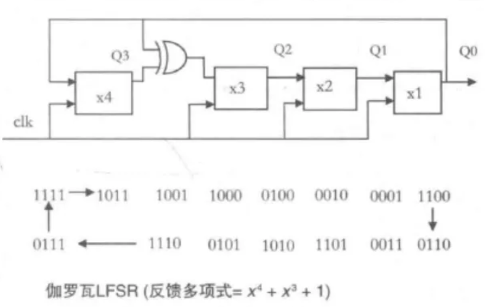
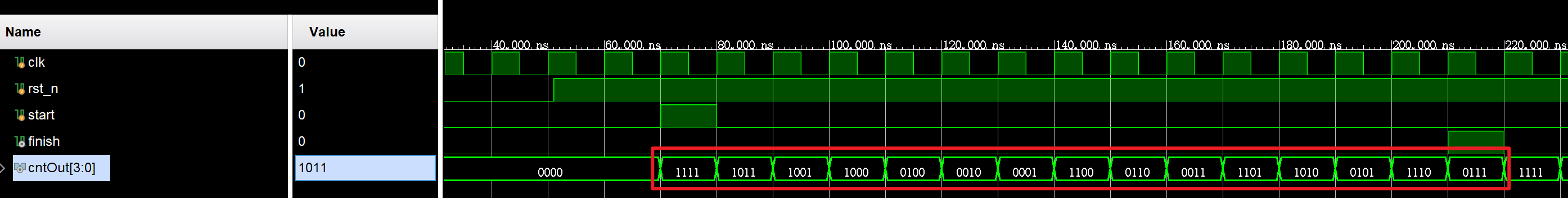
这里以伽罗瓦LFSR型(一到多)为例,实现一个4bit的LFSR计数器
重点:一到多类型的LFSR能够具有比多到一类型的LFSR更快的工作速度,因为它需要的组合逻辑级数更少。
1
2
3
4
5
6
7
8
9
10
11
12
13
14
15
16
17
18
19
20
21
22
23
24
25
26
27
28
module CNT_lfsr(
input clk ,
input rst_n ,
input start ,
output finish ,
output reg [3 : 0] cntOut
);
always @(posedge clk or negedge rst_n) begin
if(~rst_n) begin
cntOut <= 'd0;
end
else begin
if(start) begin
cntOut <= 4'b1111;
end
else begin
cntOut[0] <= cntOut[1];
cntOut[1] <= cntOut[2];
cntOut[2] <= cntOut[3] ^ cntOut[0];
cntOut[3] <= cntOut[0];
end
end
end
assign finish = (cntOut == 4'b0111) ? 1'b1 : 1'b0;
endmodule- 仿真结果:
5.PWM控制
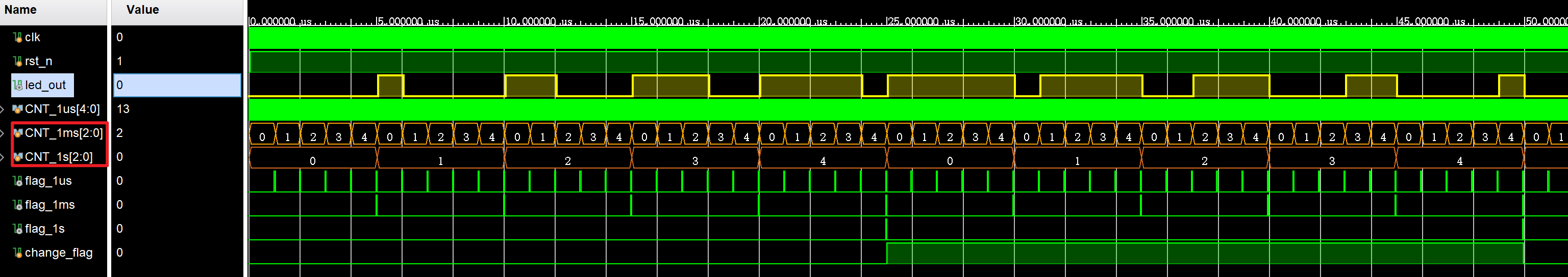
用verilog实现PWM控制呼吸灯。呼吸周期2秒:1秒逐渐变亮,1秒逐渐变暗(led_out高电平占空比多,led较亮,反之,led较暗,实现呼吸灯效果 )。系统时钟24MHz,pwm周期1ms,精度1us 。
重点:用CNT_1ms与CNT_1s去比较大小,从而得到PWM波的高电平,很妙的办法
1
2
3
4
5
6
7
8
9
10
11
12
13
14
15
16
17
18
19
20
21
22
23
24
25
26
27
28
29
30
31
32
33
34
35
36
37
38
39
40
41
42
43
44
45
46
47
48
49
50
51
52
53
54
55
56
57
58
59
60
61
62
63
64
65
66
67
68
69
70
71
72
73
74
75
76
77
78
79
80
81
82
83
84
85
86
87
88
89
90
91
92
93
94
95
96
97
98
99
100
101
102
103
104
105
module pwm_led(
input clk , //24MHz
input rst_n ,
output reg led_out
);
localparam CNT_1US_NUM = 24,
// DELAY1000 = 1000;
DELAY1000 = 5; //仿真测试时用5
reg [$clog2(CNT_1US_NUM) - 1 : 0] CNT_1us;
reg [$clog2(DELAY1000) - 1 : 0] CNT_1ms;
reg [$clog2(DELAY1000) - 1 : 0] CNT_1s;
wire flag_1us, flag_1ms, flag_1s;
reg change_flag;
//1us计数逻辑
always @(posedge clk or negedge rst_n) begin
if(~rst_n) begin
CNT_1us <= 'd0;
end
else begin
if(CNT_1us == CNT_1US_NUM - 1) begin
CNT_1us <= 'd0;
end
else begin
CNT_1us <= CNT_1us + 'd1;
end
end
end
assign flag_1us = (CNT_1us == CNT_1US_NUM - 1) ? 1'b1 : 1'b0;
//1ms计数逻辑
always @(posedge clk or negedge rst_n) begin
if(~rst_n) begin
CNT_1ms <= 'd0;
end
else begin
if(flag_1us) begin
if(CNT_1ms == DELAY1000 - 1) begin
CNT_1ms <= 'd0;
end
else begin
CNT_1ms <= CNT_1ms + 'd1;
end
end
else begin
CNT_1ms <= CNT_1ms;
end
end
end
assign flag_1ms = ((CNT_1ms == DELAY1000 - 1) && flag_1us) ? 1'b1 : 1'b0;
//1s计数逻辑
always @(posedge clk or negedge rst_n) begin
if(~rst_n) begin
CNT_1s <= 'd0;
end
else begin
if(flag_1ms) begin
if(CNT_1s == DELAY1000 - 1) begin
CNT_1s <= 'd0;
end
else begin
CNT_1s <= CNT_1s + 'd1;
end
end
else begin
CNT_1s <= CNT_1s;
end
end
end
assign flag_1s = ((CNT_1s == DELAY1000 - 1) && flag_1ms) ? 1'b1 : 1'b0;
//呼吸切换标志
always @(posedge clk or negedge rst_n) begin
if(~rst_n) begin
change_flag <= 'd0;
end
else begin
if(flag_1s) begin
change_flag <= ~change_flag;
end
else begin
change_flag <= change_flag;
end
end
end
//led输出逻辑
always @(posedge clk or negedge rst_n) begin
if(~rst_n) begin
led_out <= 'd0;
end
else begin
case(change_flag)
1'b0: led_out <= (CNT_1ms < CNT_1s) ? 1'b1 : 1'b0;
1'b1: led_out <= (CNT_1ms < CNT_1s) ? 1'b0 : 1'b1;
endcase
end
end
endmodule- 仿真结果:
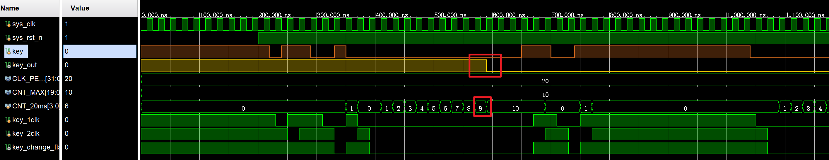
6.按键消抖
用Verilog实现按键抖动消除电路,抖动小于20ms,输入时钟50MHz
关键:计数器复0时的判断条件是检测到抖动,而不是计数满20ms,计数满20ms + 1clk时反而要将计数保持,因为按键是在计数满20ms时更新一次,如果一直保持在计数满20ms,那么按键会一直更新,所以要计数完后,要让计数保持在20ms+1clk,以等待抖动清零后再次延迟更新。
1
2
3
4
5
6
7
8
9
10
11
12
13
14
15
16
17
18
19
20
21
22
23
24
25
26
27
28
29
30
31
32
33
34
35
36
37
38
39
40
41
42
43
44
45
46
47
48
49
50
51
52
53
54
55
56
57
58
59
60
61
62
63
64
65
module key_filter(
input clk , //输入时钟50MHz
input rst_n ,
input key_in ,
output reg key_out
);
// localparam CNT_NUM = 100_0000;
localparam CNT_NUM = 10; //仿真测试用10
reg [$clog2(CNT_NUM) - 1 : 0] CNT_20ms;
reg key_1clk, key_2clk;
wire key_change_flag;
//20ms计数逻辑
always @(posedge clk or negedge rst_n) begin
if(~rst_n) begin
CNT_20ms <= 'd0;
end
else begin
if(key_change_flag) begin
CNT_20ms <= 'd0;
end
else if(CNT_20ms == CNT_NUM) begin
CNT_20ms <= CNT_20ms;
end
else begin
CNT_20ms <= CNT_20ms + 'd1;
end
end
end
//输入按键值变化判断
always @(posedge clk or negedge rst_n) begin
if(~rst_n) begin
key_1clk <= 'd1;
key_2clk <= 'd1;
end
else begin
key_1clk <= key_in;
key_2clk <= key_1clk;
end
end
//变化标志位逻辑
assign key_change_flag = key_1clk || key_2clk;
//消抖逻辑
always @(posedge clk or negedge rst_n) begin
if(~rst_n) begin
key_out <= 'd1;
end
else begin
if(CNT_20ms == CNT_NUM - 1) begin
key_out <= key_in;
end
else begin
key_out <= key_out;
end
end
end
endmodule- 仿真结果:
数据位宽转换
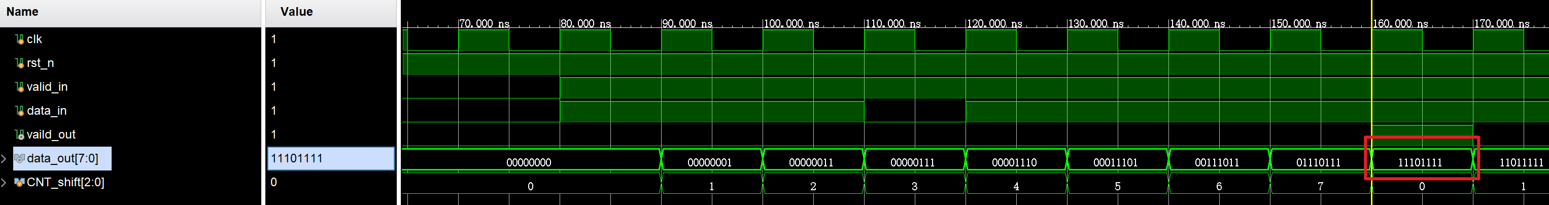
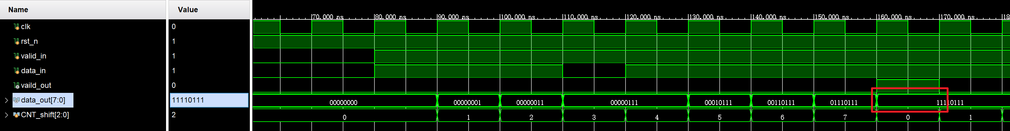
1.串转并
肯定需要有个计数器,可以用过这个计数器控制输出,也可以直接通过移位的方式,但需要计数器来指示什么时候输出数据有效
这里分为先传输最低位和先传输最高位两种情况
1
2
3
4
5
6
7
8
9
10
11
12
13
14
15
16
17
18
19
20
21
22
23
24
25
26
27
28
29
30
31
32
33
34
35
36
37
38
39
40
41
42
43
44
45
46
47
48
49
50
51
52
53
54
55
56
57
58
59
60
61
62
63
64
module Data_serial2parallel(
input clk ,
input rst_n ,
input valid_in ,
input data_in ,
output reg vaild_out ,
output reg [7 : 0] data_out
);
//移位计数器
reg [2 : 0] CNT_shift;
//计数器逻辑
always @(posedge clk or negedge rst_n) begin
if(~rst_n) begin
CNT_shift <= 'd0;
end
else begin
if(valid_in) begin
CNT_shift <= CNT_shift + 'd1;
end
else begin
CNT_shift <= 'd0;
end
end
end
//并行输出逻辑
//模式一:先传输的bit为最低位
// always @(posedge clk or negedge rst_n) begin
// if(~rst_n) begin
// data_out <= 'd0;
// end
// else begin
// data_out[CNT_shift] <= data_in;
// // data_out <= {data_in, data_out[7 : 1]}; //移位方法
// end
// end
//模式二:先传输的bit为最高
always @(posedge clk or negedge rst_n) begin
if(~rst_n) begin
data_out <= 'd0;
end
else begin
data_out[7 - CNT_shift] <= data_in;
// data_out <= {data_out[6 : 0], data_in}; //移位方法
end
end
always @(posedge clk or negedge rst_n) begin
if(~rst_n) begin
vaild_out <= 'd0;
end
else begin
if(CNT_shift == 'd7) begin
vaild_out <= 'd1;
end
else begin
vaild_out <= 'd0;
end
end
end
endmodule仿真结果
- 先传送最高位
- 先传送最低位
2.并转串
还是用移位寄存器的方式会比较快的实现,这里有做一个简单的输出有效信号逻辑
并转串主要是输入的并行data需要在串行输出没有读完时,保持不变
1
2
3
4
5
6
7
8
9
10
11
12
13
14
15
16
17
18
19
20
21
22
23
24
25
26
27
28
29
30
31
32
33
34
35
36
37
38
39
40
41
42
43
44
45
46
47
48
49
50
51
52
53
54
55
56
57
58
59
60
61
62
module Data_parallel2serial(
input clk ,
input rst_n ,
input valid_in ,
input [7 : 0] data_in ,
output reg vaild_out ,
output data_out
);
reg [7 : 0] shift_reg; //移位寄存器
reg [2 : 0] CNT_out; //输出有效计数器
always @(posedge clk or negedge rst_n) begin
if(~rst_n) begin
shift_reg <= 'd0;
end
else begin
if(valid_in) begin
shift_reg <= data_in; //寄存输入数据
end
else begin
shift_reg <= {shift_reg[0], shift_reg[7 : 1]}; //移位寄存器右移
end
end
end
assign data_out = shift_reg[0]; //从低位开始输出
always @(posedge clk or negedge rst_n) begin
if(~rst_n) begin
vaild_out <= 'd0;
end
else begin
if(valid_in) begin
vaild_out <= 'd1;
end
else begin
if(CNT_out == 'd7) begin
vaild_out <= 'd0;
end
else begin
vaild_out <= vaild_out;
end
end
end
end
always @(posedge clk or negedge rst_n) begin
if(~rst_n) begin
CNT_out <= 'd0;
end
else begin
if(vaild_out) begin
CNT_out <= CNT_out + 'd1;
end
else begin
CNT_out <= 'd0;
end
end
end
endmodule- 仿真结果:

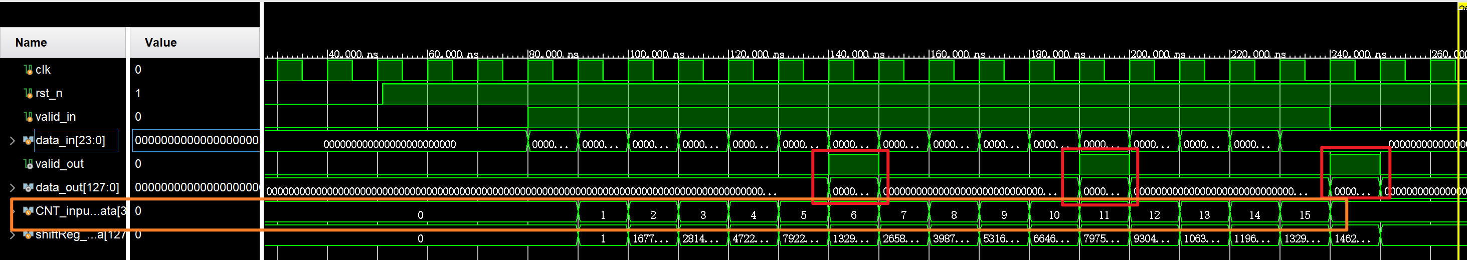
3.非整数倍24bit转128bit
实现数据位宽转换电路,实现24bit数据输入转换为128bit数据输出。其中,先到的数据应置于输出的高bit位。valid_in用来指示数据输入data_in的有效性,valid_out用来指示数据输出data_out的有效性;clk是时钟信号;rst_n是异步复位信号。
思路:找到输入输出位宽的最小公倍数
因为128×3=24×16,所以每输入16个有效数据,就可以产生三个完整的输出。因此设置一个仅在输入数据有效时工作的计数器
cnt,计数范围是0-15。
1
2
3
4
5
6
7
8
9
10
11
12
13
14
15
16
17
18
19
20
21
22
23
24
25
26
27
28
29
30
31
32
33
34
35
36
37
38
39
40
41
42
43
44
45
46
47
48
49
50
51
52
53
54
55
56
57
58
59
60
61
62
63
64
65
66
67
68
69
70
71
72
73
74
75
76
77
78
79
80
81
82
83
84
85
86
87
88
89
90
91
92
93
module Data24to128bit(
input clk ,
input rst_n ,
input valid_in ,
input [23 : 0] data_in ,
output reg valid_out ,
output reg [127 : 0] data_out
);
//输入计数器
reg [3 : 0] CNT_inputData;
//输入移位寄存器
reg [127 : 0] shiftReg_inputData;
//输入计数器逻辑
always @(posedge clk or negedge rst_n) begin
if(~rst_n) begin
CNT_inputData <= 'd0;
end
else begin
if(valid_in) begin
CNT_inputData <= CNT_inputData + 'd1;
end
else begin
CNT_inputData <= 'd0;
end
end
end
//移位寄存器逻辑
always @(posedge clk or negedge rst_n) begin
if(~rst_n) begin
shiftReg_inputData <= 'd0;
end
else begin
if(valid_in) begin
shiftReg_inputData <= {shiftReg_inputData[103 : 0], data_in};
end
else begin
shiftReg_inputData <= 'd0;
end
end
end
//根据CNT_inputData判断输出
always @(posedge clk or negedge rst_n) begin
if(~rst_n) begin
data_out <= 'd0;
end
else begin
case(CNT_inputData)
'd5: begin
data_out <= {shiftReg_inputData[119 : 0], data_in[23 -: 8]};
end
'd10: begin
data_out <= {shiftReg_inputData[111 : 0], data_in[23 -: 16]};
end
'd15: begin
data_out <= {shiftReg_inputData[103 : 0], data_in};
end
default: begin
data_out <= 'd0;
end
endcase
end
end
//输出有效信号
always @(posedge clk or negedge rst_n) begin
if(~rst_n) begin
valid_out <= 'd0;
end
else begin
case(CNT_inputData)
'd5: begin
valid_out <= 'd1;
end
'd10: begin
valid_out <= 'd1;
end
'd15: begin
valid_out <= 'd1;
end
default: begin
valid_out <= 'd0;
end
endcase
end
end
endmodule- 仿真结果:
握手协议处理
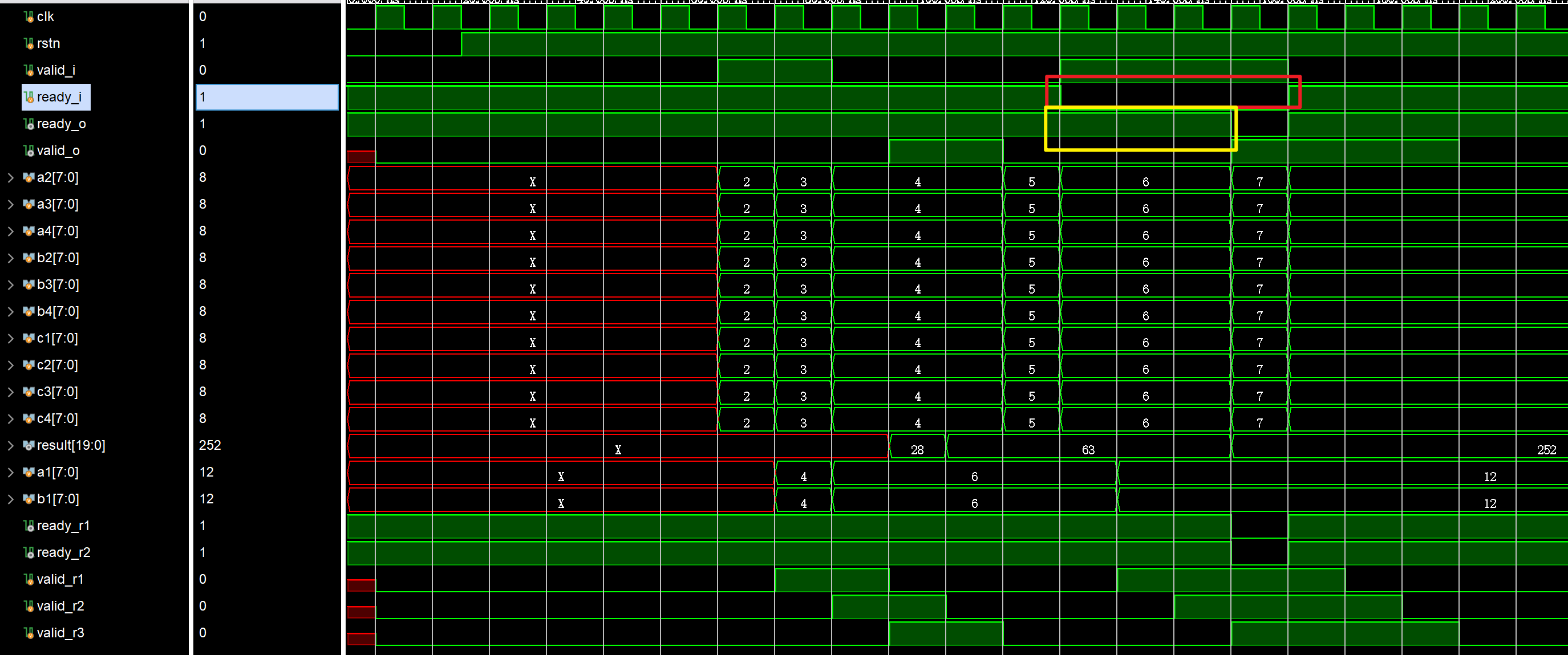
1.利用握手解决流水线断流、反压问题
详情见:数字IC手撕代码-流水握手(利用握手解决流水线断流、反压问题)_数字电路手撕代码-CSDN博客,就不粘贴完整代码了
关键:判断本级输出给上一级是否准备好的信号:当本级输出有效或者下一级没有准备好,关键代码如下:
1
2
3
4
5
6
7
8
9
10
11
12
13
14
15
16
17
18
//pipeline stage 1
assign ready_o = ~valid_r1 || ready_r1;
always @(posedge clk) begin
if(!rstn)begin
valid_r1 <= 1'b0;
end
else if(ready_o)begin //如果本级准备好了,则将上一级的valid信号传递过来
valid_r1 <= valid_i;
end
end
always @(posedge clk) begin
if(ready_o && valid_i)begin //输入数据ready_valid信号同时拉高时,数据有效并传入
a1 <= c1 + c2;
b1 <= c3 + c4;
a2_r1 <= a2; a3_r1 <= a3; a4_r1 <= a4; //数据进来打一拍到第二级流水
b2_r1 <= b2; b3_r1 <= b3; b4_r1 <= b4;
end
end仿真结果:
- 当顶层输入数据有效,但下一级反馈的ready信号无效时,该ready信号会立马反馈给本顶层模块的上一级
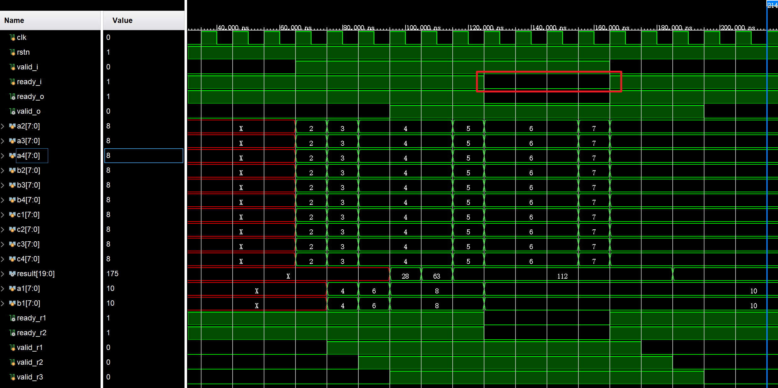
- 当输入数据无效结束后,立马拉低下一级给的ready信号,但此时不会立马反馈给上一级的ready上,因为输入数据在这之前无效了一段时间,现在流水线上是空的,只有重新把流水线填满后,该顶层模块才不能够继续输入数据了,此时才将反馈给上一级的ready拉低
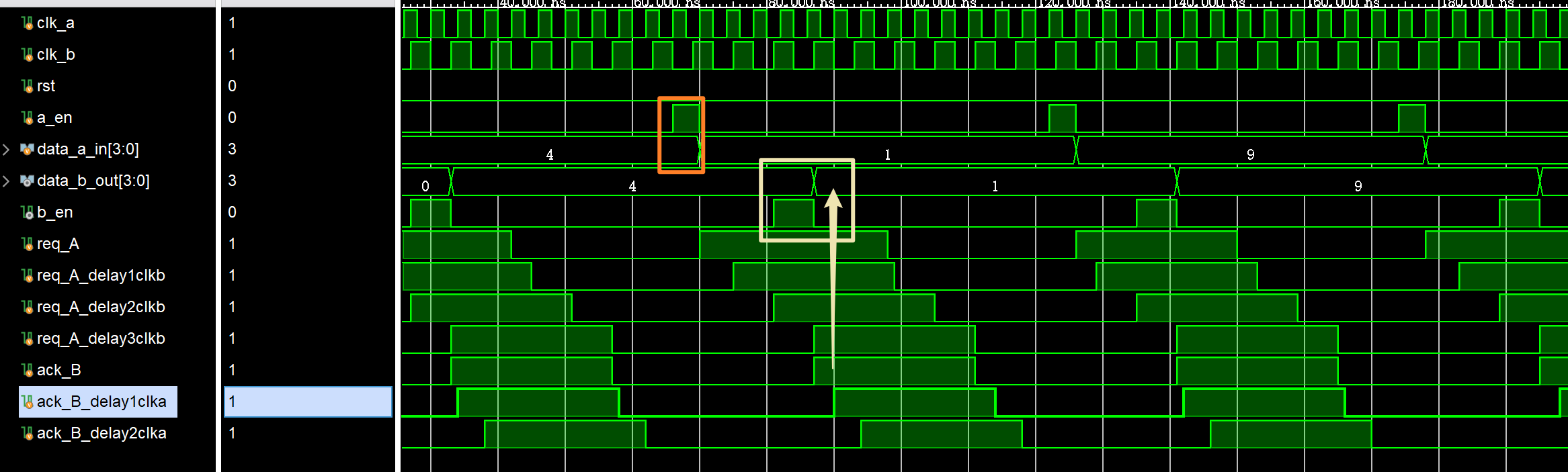
2.多bit跨时钟域握手信号
主要就是请求信号与应答信号的产生,没有特别的难点,代码如下:
1
2
3
4
5
6
7
8
9
10
11
12
13
14
15
16
17
18
19
20
21
22
23
24
25
26
27
28
29
30
31
32
33
34
35
36
37
38
39
40
41
42
43
44
45
46
47
48
49
50
51
52
53
54
55
56
57
58
59
60
61
62
63
64
65
66
67
68
69
70
71
72
73
74
75
76
77
78
79
80
81
82
83
84
85
86
87
88
89
90
91
92
93
94
95
96
97
98
99
100
101
102
103
104
105
106
107
108
109
110
module syn_handshake(
input clk_a ,
input clk_b ,
input rst_n ,
input a_en , //来自于外部的使能信号,脉冲持续一个时钟周期
input [3 : 0] data_a_in , //外部输入信号
output reg [3 : 0] data_b_out ,
output b_en ,
output ack_a
);
//A域相关变量
reg req_A;
reg ack_B_delay1clka;
reg ack_B_delay2clka;
//B域相关变量
reg req_A_delay1clkb;
reg req_A_delay2clkb;
reg req_A_delay3clkb;
reg ack_B;
//=====================A域相关操作========================
//1.产生请求信号
always @(posedge clk_a or negedge rst_n) begin
if(~rst_n) begin
req_A <= 'd0;
end
else begin
if(a_en) begin
req_A <= 'd1;
end
else if(ack_B_delay2clka) begin
req_A <= 'd0;
end
else begin
req_A <= req_A;
end
end
end
//2.同步应答信号
always @(posedge clk_a or negedge rst_n) begin
if(~rst_n) begin
ack_B_delay1clka <= 'd0;
ack_B_delay2clka <= 'd0;
end
else begin
ack_B_delay1clka <= ack_B;
ack_B_delay2clka <= ack_B_delay1clka;
end
end
assign ack_a = ack_B_delay2clka;
//=====================B域相关操作========================
//1.同步请求信号
always @(posedge clk_b or negedge rst_n) begin
if(~rst_n) begin
req_A_delay1clkb <= 'd0;
req_A_delay2clkb <= 'd0;
end
else begin
req_A_delay1clkb <= req_A;
req_A_delay2clkb <= req_A_delay1clkb;
end
end
//2.产生请求信号的上升沿标志以同步数据
always @(posedge clk_b or negedge rst_n) begin
if(~rst_n) begin
req_A_delay3clkb <= 'd0;
end
else begin
req_A_delay3clkb <= req_A_delay2clkb;
end
end
assign b_en = ~req_A_delay3clkb && req_A_delay2clkb;
//3.更新数据
always @(posedge clk_b or negedge rst_n) begin
if(~rst_n) begin
data_b_out <= 'd0;
end
else begin
if(b_en) begin
data_b_out <= data_a_in;
end
else begin
data_b_out <= data_b_out;
end
end
end
//4.产生应答信号,因为b_en在req_A_delay2clkb花费了1clk去产生响应标志
always @(posedge clk_b or negedge rst_n) begin
if(~rst_n) begin
ack_B <= 'd0;
end
else begin
ack_B <= req_A_delay2clkb;
end
end
endmodule- 仿真结果:
仲裁器设计
1.固定优先级仲裁器
固定优先级仲裁器即请求的优先级顺序是永远固定的,若规定优先级req[0]>req[1]>req[2]>req[3]…,那么则永远遵循这个优先级顺序。
重点:利用补码特性来写
- 本质上,我们要做的是找req这个信号里从低到高第一个出现的1,那么我们给req减去1会得到什么?假设req的第i位是1,第0到第i-1位都是0,那么减去1之后我们知道低位不够减,得要向高位借位,直到哪一位可以借到呢?就是第一次出现1的位,即从第i位借位,第0到i-1位都变成了1,而第i位变为了0,更高位不变。
然后我们再给减1之后的结果取反,然后把结果再和req本身按位与,可以得出,只有第i位在取反之后又变成了1,而其余位都是和req本身相反的,按位与之后是0,这样就提取出来了第一个为1的那一位,也就是我们需要的grant。
再考虑一下特殊情况req全0,很明显,按位与之后gnt依然都是全0,没有任何问题。
对二进制数来说,先减1后取反和先取反后加1得到的结果是一样的
一个数和它的补码相与,得到的结果是一个独热码,独热码为1的那一位是这个数最低的1。
1
2
3
4
5
6
7
8
9
10
module prior_arb2 #(
parameter REQ_WIDTH = 16
)(
input [REQ_WIDTH-1 : 0] req,
output [REQ_WIDTH-1 : 0] gnt
);
assign gnt = req & (~(req - 1));
endmodule
2.RR轮询仲裁器
req每一位轮流当最高优先级,详情见:仲裁器设计(2)RR轮询调度_rr仲裁器-CSDN博客
输入给定优先级的固定优先级仲裁器:
1
2
3
4
5
6
7
8
9
10
11
12
13
14
15
16
17
module arbiter_base #(
parameter NUM_REQ = 4
)(
input [NUM_REQ-1:0] req,
input [NUM_REQ-1:0] base,
output [NUM_REQ-1:0] gnt
);
wire [2 * NUM_REQ - 1 : 0] double_req;
assign double_req = {req, req};
wire [2 * NUM_REQ -1 : 0] double_gnt;
assign double_gnt = double_req & ~(double_req - base);
assign gnt = double_gnt[NUM_REQ - 1 : 0] | double_gnt[2*NUM_REQ - 1 : NUM_REQ];
endmodule在这个模块中,base是一个onehot的信号,它为1的那一位表示这一位的优先级最高,然后其次是它的高位即左边的位,直到最高位后回到第0位绕回来,优先级依次降低,直到为1那一位右边的这位为最低。咱们以4位为例,如果base = 4’b0100, 那么优先级是bit[2] > bit[3] > bit[0] > bit[1]。
这个设计的思路和前面补码特性写法很像,里面double_req & ~(double_req-base)其实就是利用减法的借位去找出base以上第一个为1的那一位,只不过由于base值可能比req值要大,不够减,所以要扩展为{req, req}来去减。当base=4‘b0001的时候就是上一节里面的最后的算法(那一节的-1相当于是-base等于4’b0001的情况)。当然base=4’b0001的时候不存在req不够减的问题,所以不用扩展。
那么好了,既然有了可以根据输入给定优先级的固定优先级仲裁器,那么接下来的任务就简单了,每次grant之后,把优先级调整一下就可以了呗。而且这个设计妙就妙在,base要求是一个onehot signal,而且为1的那一位优先级最高。我们前面说过,grant一定是onehot,grant之后被grant的那一路优先级变为最低,它的高1位优先级变为最高,
所以,只需要一个history_reg,来去记录之前最后grant的值,然后只需要将grant的值左移一下就变成了下一个周期的base。比如说,假设上一个周期grant为4’b0010,那么bit[2]要变为最高优先级,那只需要base是grant的左移即可(妙啊)
最终,RTL代码如下:
1
2
3
4
5
6
7
8
9
10
11
12
13
14
15
16
17
18
19
20
21
22
23
24
25
26
27
28
29
30
31
module round_robin_arbiter #(
parameter NUM_REQ = 4
)(
input clk,
input rstn,
input [NUM_REQ-1:0] req,
output [NUM_REQ-1:0] gnt
);
reg [NUM_REQ-1:0] hist_q, hist_d;
always @(posedge clk) begin
if(!rstn) begin
hist_q <= {{NUM_REQ-1{1'b0}}, 1'b1};
end
else begin
if(|req) begin
hist_q <= {gnt[NUM_REQ-2:0], gnt[NUM_REQ-1]};
end
end
end
arbiter_base #(
.NUM_REQ(NUM_REQ)
) arbiter(
.req (req),
.gnt (gnt),
.base (hist_q)
);
endmodule
序列检测相关
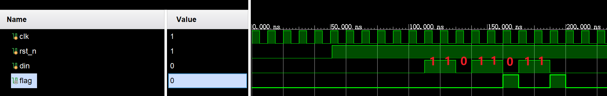
1.用最少状态机实现“11011”检测
设计一个状态机,用最少寄存器个数检测出比特序列“11011”。如果检测到这个比特序列,则状态机在下一个时钟周期输出一个时钟周期的高电平脉冲。如果检测到如下比特序列:“…110111011…”,可以认为检测到两个11011比特序列,状态机将在检测到每个11011后一个时钟周期输出一个时钟周期的高电平脉冲
思路:由于题目要求用最少状态机实现,所以下面使用的是米粒状态机,所以输出会和当前状态和输入有关,可以节省一个状态
1
2
3
4
5
6
7
8
9
10
11
12
13
14
15
16
17
18
19
20
21
22
23
24
25
26
27
28
29
30
31
32
33
34
35
36
37
38
39
40
41
42
43
44
45
46
47
48
49
50
51
52
53
54
module seqDetect_11011(
input clk ,
input rst_n ,
input din ,
output reg flag
);
//状态定义
localparam IDLE = 5'b00001, //空闲
S1 = 5'b00010, //'1'
S2 = 5'b00100, //'11'
S3 = 5'b01000, //'110'
S4 = 5'b10000; //'1101'
reg [4 : 0] cur_state, next_state;
//状态跳转
always @(posedge clk or negedge rst_n) begin
if(~rst_n) begin
cur_state <= IDLE;
end
else begin
cur_state <= next_state;
end
end
//次态判断
always @(*) begin
next_state = cur_state;
case(cur_state)
IDLE: next_state = din ? S1 : IDLE;
S1 : next_state = din ? S2 : IDLE;
S2 : next_state = din ? S2 : S3;
S3 : next_state = din ? S4 : IDLE;
S4 : next_state = din ? S2 : IDLE;
endcase
end
//输出时序逻辑
always @(posedge clk or negedge rst_n) begin
if(~rst_n) begin
flag <= 'd0;
end
else begin
if(cur_state == S4 && din == 1'b1) begin
flag <= 'd1;
end
else begin
flag <= 'd0;
end
end
end
endmodule- 仿真结果:
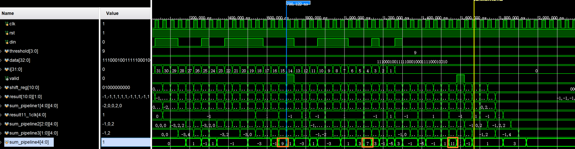
2.巴克码检测器
设计一个巴克码检测器,输入是1位序列,需要先移至移位寄存器中,再将移位寄存器中的值与标准巴克码同或,通过判断同或值是否大于阈值来确定巴克码,给定巴克码序列为11’b11100010010
按照题目描述写就好,要注意的地方是这里的同或值指的是,同或结果为1,同或值加1,同或结果为0,同或值-1
易错点:这里写代码的时候发现,verilog中的比较器,在进行有符号与无符号的比较时,会出错,错误代码如下:
1
2
3
4
5
6
7
8
9
10
11
12
13
always @(posedge clk or negedge rst_n) begin
if(~rst_n) begin
valid <= 'd0;
end
else begin
if($signed(sum_pipeline4) >= threshold) begin
valid <= 'd1;
end
else begin
valid <= 'd0;
end
end
end解决上述问题的办法:要么将无符号数转化为有符号数一起比较,要么按下面代码中的处理方式
1
2
3
4
5
6
7
8
9
10
11
12
13
14
15
16
17
18
19
20
21
22
23
24
25
26
27
28
29
30
31
32
33
34
35
36
37
38
39
40
41
42
43
44
45
46
47
48
49
50
51
52
53
54
55
56
57
58
59
60
61
62
63
64
65
66
67
68
69
70
71
72
73
74
75
76
77
78
79
80
81
82
83
84
85
86
87
88
89
90
91
92
93
94
95
96
97
98
99
100
101
102
103
104
105
106
107
108
109
110
111
112
113
114
115
116
117
118
119
120
121
122
123
124
125
126
127
128
129
130
131
132
133
134
135
136
137
138
139
140
141
142
143
144
145
146
147
148
149
150
151
152
153
154
155
156
module buc(
input clk ,
input rst_n ,
input din ,
input [3 : 0] threshold ,
output reg valid
);
localparam REF_BUC = 11'b11100010010;
reg [10 : 0] shift_reg; //移位寄存器
reg signed [1 : 0] result [10 : 0]; //同或结果,同或结果为0的直接赋值为-1,即2'b11;
//加法树第一级流水线变量
reg signed [4 : 0] sum_pipeline1 [4 : 0];
reg signed [4 : 0] result11_1clk;
//加法树第二级流水线变量
reg signed [4 : 0] sum_pipeline2 [2 : 0];
//加法树第三级流水线变量
reg signed [4 : 0] sum_pipeline3 [1 : 0];
//加法树第四级流水线变量
reg signed [4 : 0] sum_pipeline4;
//移位寄存器逻辑
always @(posedge clk or negedge rst_n) begin
if(~rst_n) begin
shift_reg <= 'd0;
end
else begin
shift_reg <= {shift_reg[9 : 0], din};
end
end
//移位寄存器与标准巴克码同或
generate
genvar i;
for(i = 0; i < 11; i = i + 1) begin: shift_compare_result
always @(posedge clk or negedge rst_n) begin
if(~rst_n) begin
result[i] <= 'd0;
end
else begin
if(shift_reg[i] ^~ REF_BUC[i]) begin
result[i] <= 'd1;
end
else begin
result[i] <= -'d1;
end
end
end
end
endgenerate
//加法树求和以得到同或值
//流水线1
always @(posedge clk or negedge rst_n) begin
if(~rst_n) begin
result11_1clk <= 'd0;
end
else begin
result11_1clk <= result[10];
end
end
generate
genvar j;
for(j = 0; j < 5; j = j + 1) begin: sum_pipeline1_unit
always @(posedge clk or negedge rst_n) begin
if(~rst_n) begin
sum_pipeline1[j] <= 'd0;
end
else begin
sum_pipeline1[j] <= result[j * 2 + 1] + result[j * 2];
end
end
end
endgenerate
//流水线2
always @(posedge clk or negedge rst_n) begin
if(~rst_n) begin
sum_pipeline2[0] <= 'd0;
end
else begin
sum_pipeline2[0] <= sum_pipeline1[1] + sum_pipeline1[0];
end
end
always @(posedge clk or negedge rst_n) begin
if(~rst_n) begin
sum_pipeline2[1] <= 'd0;
end
else begin
sum_pipeline2[1] <= sum_pipeline1[3] + sum_pipeline1[2];
end
end
always @(posedge clk or negedge rst_n) begin
if(~rst_n) begin
sum_pipeline2[2] <= 'd0;
end
else begin
sum_pipeline2[2] <= sum_pipeline1[4] + result11_1clk;
end
end
//流水线3
always @(posedge clk or negedge rst_n) begin
if(~rst_n) begin
sum_pipeline3[0] <= 'd0;
end
else begin
sum_pipeline3[0] <= sum_pipeline2[0] + sum_pipeline2[1];
end
end
always @(posedge clk or negedge rst_n) begin
if(~rst_n) begin
sum_pipeline3[1] <= 'd0;
end
else begin
sum_pipeline3[1] <= sum_pipeline2[2];
end
end
//流水线4
always @(posedge clk or negedge rst_n) begin
if(~rst_n) begin
sum_pipeline4 <= 'd0;
end
else begin
sum_pipeline4 <= sum_pipeline3[0] + sum_pipeline3[1];
end
end
//阈值比较输出逻辑
always @(posedge clk or negedge rst_n) begin
if(~rst_n) begin
valid <= 'd0;
end
else begin
if(sum_pipeline4[4] == 0) begin
if(sum_pipeline4[3 : 0] >= threshold) begin
valid <= 'd1;
end
else begin
valid <= 'd0;
end
end
else begin
valid <= 'd0;
end
end
end
endmodule- 仿真结果:
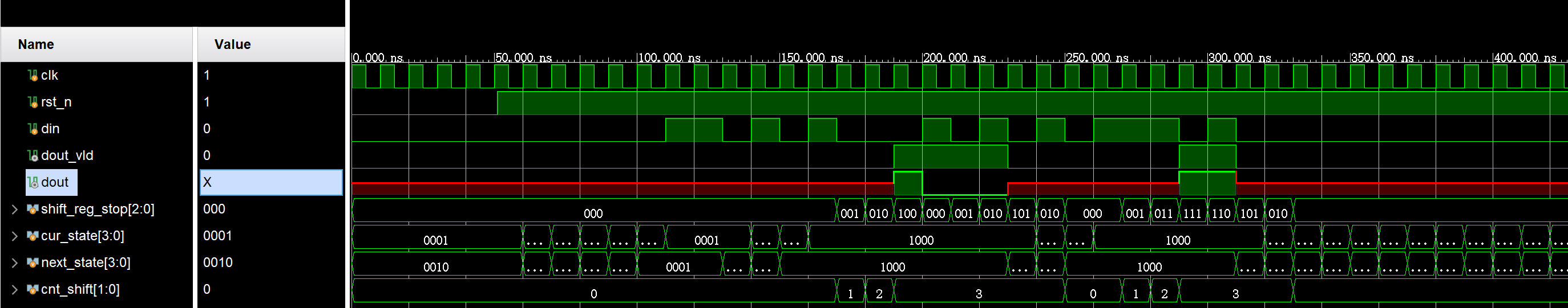
3.输入“010”开始,输入“101”停止的序列检测
请编写一个序列检测模块,当输入010时开始输出序列,当输入101时停止输出序列如输入din为11010100010101011101,输出dout为xxxx1000xxxxxx11xxx, dout_vld为00000111100000011000
思考:初看题目移位一个移位寄存器就能解决问题,结果发现这里面有两个坑。第一大坑:如果只用移位寄存器,那么移位寄存器里面的值会被重复利用的,比如010之后如果跟一个1,实际上代表的是开始标志后跟了一个正确数据1,但移位寄存器那么做的话,会认为前一拍是010,后一拍是101,10被复用了,从而会导致识别到的是开始又停止。第二大坑:其实可以说是本题难点吧,就是101的数据不要输出,只输出101之前的数据,但我得先判断是否是101,才能知道是否停止,有种提前预知的感觉。
解决办法:针对第一大坑,我把开始标志检测和输出数据用状态机隔开了,而结束标志是在输出数据的状态,用移位寄存器去判断的。针对第二大坑,采用的方法是,移位寄存器的作用不仅是缓存数据以判断停止标志,有一个更关键的点在于,我在移位寄存器中,先移入3拍数据,判断是否是停止标志后,再输出这3拍数据中的最旧的那个数据,即下面代码中的
shift_reg_stop[2]1
2
3
4
5
6
7
8
9
10
11
12
13
14
15
16
17
18
19
20
21
22
23
24
25
26
27
28
29
30
31
32
33
34
35
36
37
38
39
40
41
42
43
44
45
46
47
48
49
50
51
52
53
54
55
56
57
58
59
60
61
62
63
64
65
66
67
68
69
70
71
72
73
74
75
76
77
78
79
80
81
82
83
84
85
86
87
88
89
90
91
92
93
94
95
96
97
98
99
100
101
102module seqDetect_start010Stop101(
input clk ,
input rst_n ,
input din ,
output dout ,
output dout_valid
);
reg [2 : 0] shift_reg_stop; //结束的移位寄存器
reg [1 : 0] cnt_shift; //移位计数器,要等当前三个数据都移进来后再判断
//状态定义
localparam IDLE = 4'b0001,
DETECT0 = 4'b0010,
DETECT01 = 4'b0100,
OUTDATA = 4'b1000;
//现态与次态定义
reg [3 : 0] cur_state, next_state;
//状态跳转
always @(posedge clk or negedge rst_n) begin
if(~rst_n) begin
cur_state <= IDLE;
end
else begin
cur_state <= next_state;
end
end
//次态判断
always @(*) begin
next_state = cur_state;
case(cur_state)
IDLE: begin
next_state = din ? IDLE : DETECT0;
end
DETECT0: begin
next_state = din ? DETECT01 : IDLE;
end
DETECT01: begin
next_state = din ? IDLE : OUTDATA;
end
OUTDATA: begin
if(shift_reg_stop == 3'b101) begin
if(din) begin
next_state = IDLE;
end
else begin
next_state = DETECT0;
end
end
else begin
next_state = OUTDATA;
end
end
endcase
end
//停止移位寄存器逻辑
always @(posedge clk or negedge rst_n) begin
if(~rst_n) begin
shift_reg_stop <= 'd0;
end
else begin
if(cur_state == OUTDATA) begin
shift_reg_stop <= {shift_reg_stop[1 : 0], din};
end
else begin
shift_reg_stop <= 'd0;
end
end
end
//移位计数器逻辑
always @(posedge clk or negedge rst_n) begin
if(~rst_n) begin
cnt_shift <= 'd0;
end
else begin
if(cur_state == OUTDATA) begin
if(cnt_shift == 3) begin
cnt_shift <= cnt_shift;
end
else begin
cnt_shift <= cnt_shift + 'd1;
end
end
else begin
cnt_shift <= 'd0;
end
end
end
//输出逻辑
assign dout_valid = (cur_state == OUTDATA) && (cnt_shift == 'd3) && (shift_reg_stop != 3'b101);
assign dout = dout_valid ? shift_reg_stop[2] : 'dx;
endmodule- 仿真结果:
典型状态机
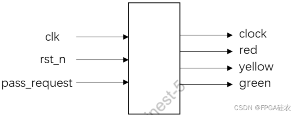
1.交通灯设计
要求实现一个交通红绿灯,具有红黄绿三个小指示灯和一个行人按钮,正常情况下,机动车道指示灯按照60时钟周期绿灯,5个时钟周期黄灯,10个时钟周期红灯循环。当行人按钮按下,如果剩余绿灯时间大于10个时钟,则缩短为10个时钟,小于10个时钟则保持不变
1
2
3
4
5
6
7
8
9
10
11
12
13
14
15
16
17
18
19
20
21
22
23
24
25
26
27
28
29
30
31
32
33
34
35
36
37
38
39
40
41
42
43
44
45
46
47
48
49
50
51
52
53
54
55
56
57
58
59
60
61
62
63
64
65
66
67
68
69
70
71
72
73
74
75
76
77
78
79
80
81
82
83
84
85
86
87
88
89
90
91
92
93
94
95
96
97
98
99
100
101
102
103
104
105
106
107
108
109
110
111
112
113
114
115
116
117
118
119
120
121
122
123
124
125
126
127
128
129
130
131
132
133
134
135module traffic_light(
input clk ,
input rst_n ,
input pass_request ,
output reg [7 : 0] clock ,
output reg red ,
output reg yellow ,
output reg green
);
//状态定义
localparam GREEN_TIME = 3'b001,
YELLOW_TIME = 3'b010,
RED_TIME = 3'b100;
//现态与次态
reg [2 : 0] cur_state, next_state;
//状态跳转
always @(posedge clk or negedge rst_n) begin
if(~rst_n) begin
cur_state <= GREEN_TIME;
end
else begin
cur_state <= next_state;
end
end
//次态判断
always @(*) begin
next_state = cur_state;
case(cur_state)
GREEN_TIME: begin
if(clock == 1) begin
next_state = YELLOW_TIME;
end
else begin
next_state = GREEN_TIME;
end
end
YELLOW_TIME: begin
if(clock == 1) begin
next_state = RED_TIME;
end
else begin
next_state = YELLOW_TIME;
end
end
RED_TIME: begin
if(clock == 1) begin
next_state = GREEN_TIME;
end
else begin
next_state = RED_TIME;
end
end
default: next_state = RED_TIME;
endcase
end
//clock计数逻辑
always @(posedge clk or negedge rst_n) begin
if(~rst_n) begin
clock <= 'd10;
end
else begin
case(cur_state)
GREEN_TIME: begin
if(clock == 1) begin
clock <= 'd5;
end
else begin
if(pass_request) begin
if(clock > 10) begin
clock <= 'd10;
end
else begin
clock <= clock - 'd1;
end
end
else begin
clock <= clock - 'd1;
end
end
end
YELLOW_TIME: begin
if(clock == 1) begin
clock <= 'd10;
end
else begin
clock <= clock - 'd1;
end
end
RED_TIME: begin
if(clock == 1) begin
clock <= 'd60;
end
else begin
clock <= clock - 'd1;
end
end
endcase
end
end
//输出逻辑
always @(*) begin
red = 'd0;
yellow = 'd0;
green = 'd0;
case(cur_state)
GREEN_TIME: begin
red = 'd0;
yellow = 'd0;
green = 'd1;
end
YELLOW_TIME: begin
red = 'd0;
yellow = 'd1;
green = 'd0;
end
RED_TIME: begin
red = 'd1;
yellow = 'd0;
green = 'd0;
end
default: begin
red = 'd1;
yellow = 'd0;
green = 'd0;
end
endcase
end
endmodule
2.饮料机设计
饮料单价2元,该售卖机只接受0.5元、1元的硬币。考虑找零和出货。投币和出货过程都是一次一次的进行,不会出现一次性投入多币或一次性出货多瓶饮料的现象。每一轮售卖机接受投币、出货、找零完成后,才能进入到新的自动售卖状态。其中,coin = 1代表投入了0.5元硬币,coin=2代表投入了1元硬币
以下代码采用Mealy型状态机设计,状态是根据投入钱数(<2[单价])设定的。如果要用moore型,则状态是根据所有可能出现的总投币值设定的
1
2
3
4
5
6
7
8
9
10
11
12
13
14
15
16
17
18
19
20
21
22
23
24
25
26
27
28
29
30
31
32
33
34
35
36
37
38
39
40
41
42
43
44
45
46
47
48
49
50
51
52
53
54
55
56
57
58
59
60
61
62
63
64
65
66
67
68
69
70
71
72
73
74
75
76
77
78
79
80
81
82
83
84
85
86
87
88
89
module vending_machine_p3(
input clk ,
input rstn ,
input [1 : 0] coin , //等于1代表投入0.5元,等于2代表投入1元
output [1 : 0] change , //找零
output sell
);
//状态定义
localparam IDLE = 4'b0001,
GET05 = 4'b0010, //当前投入0.5元
GET10 = 4'b0100, //当前投入1元
GET15 = 4'b1000; //当前投入1.5元
//次态与现态
reg [3 : 0] cur_state, next_state;
//输出变量
reg [1 : 0] change_r;
reg sell_r;
//状态跳转
always @(posedge clk or negedge rstn) begin
if(~rstn) begin
cur_state <= IDLE;
end
else begin
cur_state <= next_state;
end
end
//次态判断
always @(*) begin
next_state = cur_state;
case(cur_state)
IDLE: next_state = (coin == 1) ? GET05 : ((coin == 2) ? GET10 : IDLE);
GET05: next_state = (coin == 1) ? GET10 : ((coin == 2) ? GET15 : GET05);
GET10: next_state = (coin == 1) ? GET15 : ((coin == 2) ? IDLE : GET10);
GET15: next_state = (coin == 1) ? IDLE : ((coin == 2) ? IDLE : GET15);
default: next_state = IDLE;
endcase
end
//输出逻辑
always @(posedge clk or negedge rstn) begin
if(~rstn) begin
change_r <= 'd0;
end
else begin
case(cur_state)
IDLE: change_r <= 'd0;
GET05: change_r <= 'd0;
GET10: change_r <= 'd0;
GET15: begin
case(coin)
2'd1: change_r <= 'd0;
2'd2: change_r <= 'd1;
default: change_r <= 'd0;
endcase
end
endcase
end
end
always @(posedge clk or negedge rstn) begin
if(~rstn) begin
sell_r <= 'd0;
end
else begin
case(cur_state)
IDLE: sell_r <= 'd0;
GET05: sell_r <= 'd0;
GET10: begin
case(coin)
2'd1: sell_r <= 'd0;
2'd2: sell_r <= 'd1;
default: sell_r <= 'd0;
endcase
end
GET15: sell_r <= 'd1;
default: sell_r <= 'd0;
endcase
end
end
assign sell = sell_r;
assign change = change_r;
endmodule
3.模三检测器
对输入的单比特数据流进行模三检测,如果数据能被3整除,则拉高flag信号
解题思路参考:
根据余数设定状态【S0(余数为0)、S1(余数为1)、S2(余数为2)】,故包括IDLE状态在内,共有4个状态

上述表格很清晰,需要注意的是,当输入1bit时,原来余数就会*2,以当前余数是2时为例,此时输入为0,次态余数为$(2\times 2)\%3 = 1$,此时输入为1,次态余数为$(2\times 2 + 1)\%3 = 2$
1
2
3
4
5
6
7
8
9
10
11
12
13
14
15
16
17
18
19
20
21
22
23
24
25
26
27
28
29
30
31
32
33
34
35
36
37
38
39
40
41
42
43
44
45
46
47
48
49
50
51
52
//模3检测器*
module mode3_det(
input clk ,
input rst_n ,
input data ,
output reg flag
);
//状态定义
parameter IDEL = 4'b0001,
S0 = 4'b0010, //余数为0
S1 = 4'b0100, //余数为1
S2 = 4'b1000; //余数为2
//现态与次态
reg [3 : 0] cur_state, next_state;
//状态跳转
always @(posedge clk or negedge rst_n) begin
if(~rst_n) begin
cur_state <= IDEL;
end
else begin
cur_state <= next_state;
end
end
//次态判读
always @(*) begin
next_state = cur_state;
case(cur_state)
IDEL: next_state = data ? S1 : S0;
S0: next_state = data ? S1 : S0;
S1: next_state = data ? S0 : S2;
S2: next_state = data ? S2 : S1;
default: next_state = IDEL;
endcase
end
//结果输出
always @(posedge clk or negedge rst_n) begin
if(~rst_n) begin
flag <= 1'b0;
end
else begin
flag <= (next_state == S0) ? 1 : 0;
end
end
endmodule
4.布斯乘法设计
计算流程见:补码一位乘法——布斯(Booth)算法_布斯算法-CSDN博客
1
2
3
4
5
6
7
8
9
10
11
12
13
14
15
16
17
18
19
20
21
22
23
24
25
26
27
28
29
30
31
32
33
34
35
36
37
38
39
40
41
42
43
44
45
46
47
48
49
50
51
52
53
54
55
56
57
58
59
60
61
62
63
64
65
66
67
68
69
70
71
72
73
74
75
76
77
78
79
80
81
82
83
84
85
86
87
88
89
90
91
92
module booth_multiple(
input clk ,
input rst ,
input start ,
input signed [3 : 0] X ,
input signed [3 : 0] Y ,
output reg signed [7 : 0] Z ,
output valid
);
//状态定义
localparam IDLE = 3'b001,
CACULATE = 3'b010,
FINISH = 3'b100;
//现态与次态定义
reg [2 : 0] cur_state, next_state;
//其他变量定义
reg [1 : 0] q_res; //右移最后两位寄存
reg [2 : 0] cnt; //右移计数信号
//状态跳转逻辑
always @(posedge clk or posedge rst) begin
if(rst) begin
cur_state <= IDLE;
end
else begin
cur_state <= next_state;
end
end
//次态判断
always @(*) begin
next_state = cur_state;
case(cur_state)
IDLE: begin
next_state = start ? CACULATE : IDLE;
end
CACULATE: begin
next_state = (cnt == 3) ? FINISH : CACULATE;
end
FINISH: begin
next_state = IDLE;
end
default: begin
next_state = IDLE;
end
endcase
end
//结果输出逻辑
always @(posedge clk or posedge rst) begin
if(rst) begin
q_res <= 'd0;
cnt <= 'd0;
Z <= 'd0;
end
else begin
case(cur_state)
IDLE: begin
cnt <= 'd0;
q_res <= {Y[cnt], 1'b0};
Z <= {4'b0000, Y};
end
CACULATE: begin
cnt <= cnt + 'd1;
q_res <= {Y[cnt + 1], Y[cnt]};
case(q_res)
2'b00, 2'b11: begin
Z = $signed(Z) >>> 1;
end
2'b01: begin
Z = $signed({Z[7 : 4] + X, Z[3 : 0]}) >>> 1;
end
2'b10: begin
Z = $signed({Z[7 : 4] - X, Z[3 : 0]}) >>> 1;
end
endcase
end
FINISH: begin
cnt <= 'd0;
q_res <= 'd0;
Z <= Z;
end
endcase
end
end
assign valid = (cur_state == FINISH) ? 1'b1 : 1'b0;
endmodule
时钟分频
- 分频电路图可参考:常用电路设计——“分频电路” - 知乎
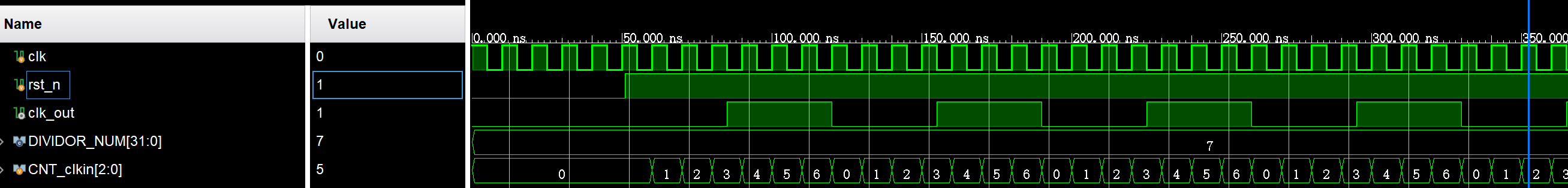
1.任意偶数分频
偶数分频除了下面方法外,其实也可以根据计数器的变化得出分频结果,比如8分频就为
clk_out = CNT_clkin[3]1
2
3
4
5
6
7
8
9
10
11
12
13
14
15
16
17
18
19
20
21
22
23
24
25
26
27
28
29
30
31
32
33
34
35
36
37
38
39module clk_evenDivider #(
parameter DIVIDOR_NUM = 8
)(
input clk ,
input rst_n ,
output reg clk_out
);
reg [$clog2(DIVIDOR_NUM) - 1 : 0] CNT_clkin;
always @(posedge clk or negedge rst_n) begin
if(~rst_n) begin
CNT_clkin <= 'd0;
end
else begin
if(CNT_clkin == DIVIDOR_NUM - 1) begin
CNT_clkin <= 'd0;
end
else begin
CNT_clkin <= CNT_clkin + 1;
end
end
end
always @(posedge clk or negedge rst_n) begin
if(~rst_n) begin
clk_out <= 'd0;
end
else begin
if(CNT_clkin == DIVIDOR_NUM / 2 - 1 || CNT_clkin == DIVIDOR_NUM - 1) begin
clk_out <= ~clk_out;
end
else begin
clk_out <= clk_out;
end
end
end
endmodule- 仿真结果:

2.任意奇数分频
重点:分别利用上升沿和下降沿对计数器进行判断,最后对结果取或
1
2
3
4
5
6
7
8
9
10
11
12
13
14
15
16
17
18
19
20
21
22
23
24
25
26
27
28
29
30
31
32
33
34
35
36
37
38
39
40
41
42
43
44
45
46
47
48
49
50
51
52
53
54
55
56
57
58
59
60
61module clk_oddDivider #(
parameter DIVIDOR_NUM = 5
)(
input clk ,
input rst_n ,
output clk_out
);
reg [$clog2(DIVIDOR_NUM) - 1 : 0] CNT_clkin; //输入时钟计数器
reg clk_up, clk_down; //上升沿判断时钟与下降沿判断时钟
//计数器逻辑
always @(posedge clk or negedge rst_n) begin
if(~rst_n) begin
CNT_clkin <= 'd0;
end
else begin
if(CNT_clkin == DIVIDOR_NUM - 1) begin
CNT_clkin <= 'd0;
end
else begin
CNT_clkin <= CNT_clkin + 'd1;
end
end
end
//上升沿逻辑
always @(posedge clk or negedge rst_n) begin
if(~rst_n) begin
clk_up <= 'd0;
end
else begin
if(CNT_clkin == DIVIDOR_NUM / 2 || CNT_clkin == DIVIDOR_NUM - 1) begin
clk_up <= ~clk_up;
end
else begin
clk_up <= clk_up;
end
end
end
//下降沿逻辑
always @(negedge clk or negedge rst_n) begin
if(~rst_n) begin
clk_down <= 'd0;
end
else begin
if(CNT_clkin == DIVIDOR_NUM / 2 || CNT_clkin == DIVIDOR_NUM - 1) begin
clk_down <= ~clk_down;
end
else begin
clk_down <= clk_down;
end
end
end
//奇数分频时钟输出
assign clk_out = clk_up || clk_down;
endmodule- 仿真结果:
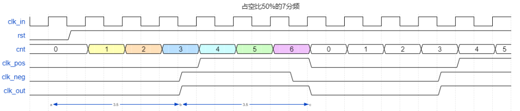
3.小数分频
设计一个6.3分频
关键:6.3等效为63/10,相当于输入63个时钟周期,输出10个时钟周期,而这10个时钟周期通常用会用两个小分频来组成,通常取小数附近的两个整数分频来表示,比如6<6.3<7,就用6分频和7分频的组合来表示6.3分频,上述描述存在两个等式,即:
其中,$x$表示10个输出时钟中有$x$个6分频,$y$表示10个输出时钟中有$y$个7分频
1
2
3
4
5
6
7
8
9
10
11
12
13
14
15
16
17
18
19
20
21
22
23
24
25
26
27
28
29
30
31
32
33
34
35
36
37
38
39
40
41
42
43
44
45
46
47
48
49
50
51
52
53
54
55
56
57
58
59
60
61
62
63
64
65
66
67
68
69
70
71
72
73
74
75
76
77
78
79
80
81
82
83
84
85
86
87
88
89
90
91
92
93
94
95
96
97
98
99
100//6.3小数分频
//输出7个6分频,3个7分频的循环
module clk_pointDivider(
input clk ,
input rst_n ,
output reg clk_out
);
localparam INPUTCLK_CYCLE = 63 ,
CHANGE_CYCLE = 42 ,
DIVIDE1 = 6 ,
DIVIDE2 = 7 ;
reg [$clog2(INPUTCLK_CYCLE) - 1 : 0] CNT_inputClk; //输入计数器
reg change_flag; //切换标志位
reg [2 : 0] CNT_inter; //分频内部计数器
//输入时钟计数器逻辑
always @(posedge clk or negedge rst_n) begin
if(~rst_n) begin
CNT_inputClk <= 'd0;
end
else begin
if(CNT_inputClk == INPUTCLK_CYCLE - 1) begin
CNT_inputClk <= 'd0;
end
else begin
CNT_inputClk <= CNT_inputClk + 'd1;
end
end
end
//切换标志位逻辑
always @(posedge clk or negedge rst_n) begin
if(~rst_n) begin
change_flag <= 'd0;
end
else begin
if(CNT_inputClk == CHANGE_CYCLE - 1 || CNT_inputClk == INPUTCLK_CYCLE - 1) begin
change_flag <= ~change_flag;
end
else begin
change_flag <= change_flag;
end
end
end
//分频内部计数器逻辑
always @(posedge clk or negedge rst_n) begin
if(~rst_n) begin
CNT_inter <= 'd0;
end
else begin
if(~change_flag) begin //对于DIVIDE1情况
if(CNT_inter == DIVIDE1 - 1) begin
CNT_inter <= 'd0;
end
else begin
CNT_inter <= CNT_inter + 'd1;
end
end
else begin //对于DIVIDE2情况
if(CNT_inter == DIVIDE2 - 1) begin
CNT_inter <= 'd0;
end
else begin
CNT_inter <= CNT_inter + 'd1;
end
end
end
end
//输出时钟逻辑
always @(posedge clk or negedge rst_n) begin
if(~rst_n) begin
clk_out <= 'd0;
end
else begin
if(~change_flag) begin
if(CNT_inter == DIVIDE1 / 2 - 1 || CNT_inter == DIVIDE1 - 1) begin
clk_out <= ~clk_out;
end
else begin
clk_out <= clk_out;
end
end
else begin
if(CNT_inter == DIVIDE2 / 2 || CNT_inter == DIVIDE2 - 1) begin
clk_out <= ~clk_out;
end
else begin
clk_out <= clk_out;
end
end
end
end
endmodule- 仿真结果:

同步/异步相关
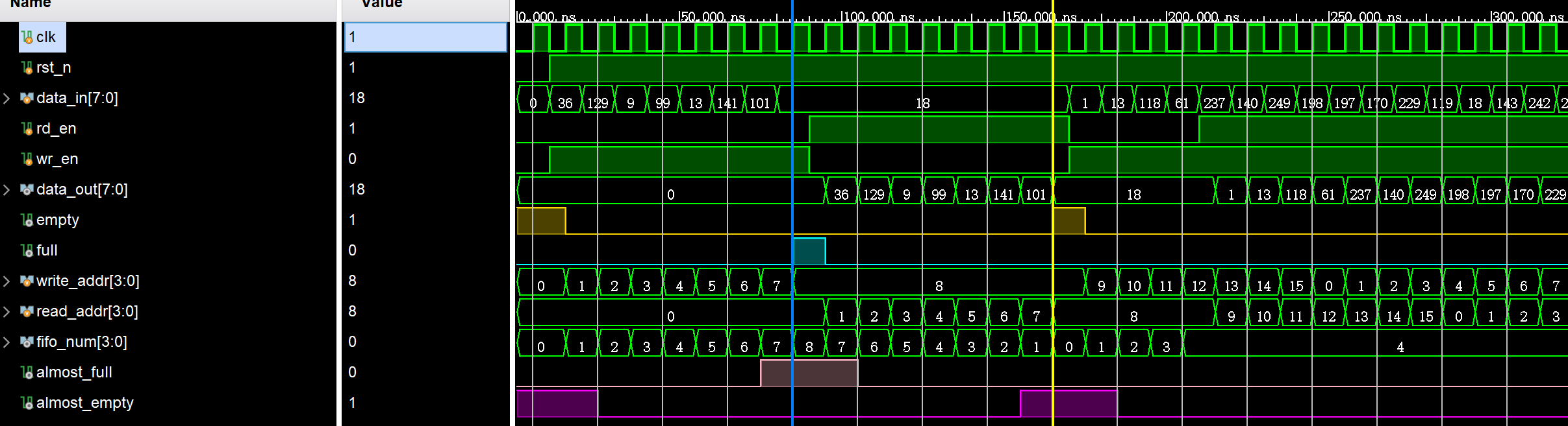
1.同步FIFO
重点:fifo中目标已有的数量,等于扩展1bit后的写地址-读地址,fifo_num也要扩展1bit,毕竟3bit是无法表示8的
1
2
3
4
5
6
7
8
9
10
11
12
13
14
15
16
17
18
19
20
21
22
23
24
25
26
27
28
29
30
31
32
33
34
35
36
37
38
39
40
41
42
43
44
45
46
47
48
49
50
51
52
53
54
55
56
57
58
59
60
61
62
63
64
65
66
67
68
69
70
71
72
73
74
75
76
77
78
79
80
81
82
83
84
85
86
87
88
89
90
91
92module sync_fifo_test #(
parameter DATA_WIDTH = 16,
FIFO_DEPTH = 8 ,
ALMOST_FULL_DEPTH = 7 ,
ALMOST_EMPTY_DEPTH = 1
)(
input clk ,
input rst_n ,
input wr_en ,
input rd_en ,
input [DATA_WIDTH - 1 : 0] data_write ,
output reg [DATA_WIDTH - 1 : 0] data_read ,
output full ,
output empty ,
output almost_full ,
output almost_empty
);
reg [DATA_WIDTH - 1 : 0] BRAM [FIFO_DEPTH - 1 : 0]; //定义BRAM
reg [$clog2(FIFO_DEPTH) : 0] write_addr; //扩展1bit
reg [$clog2(FIFO_DEPTH) : 0] read_addr;
//写地址逻辑
always @(posedge clk or negedge rst_n) begin
if(~rst_n) begin
write_addr <= 'd0;
end
else begin
if(wr_en && ~full) begin
write_addr <= write_addr + 'd1;
end
else begin
write_addr <= write_addr;
end
end
end
//读地址逻辑
always @(posedge clk or negedge rst_n) begin
if(~rst_n) begin
read_addr <= 'd0;
end
else begin
if(rd_en && ~empty) begin
read_addr <= read_addr + 'd1;
end
else begin
read_addr <= read_addr;
end
end
end
//写数据逻辑
integer i;
always @(posedge clk or negedge rst_n) begin
if(~rst_n) begin
for(i = 0; i < FIFO_DEPTH; i = i + 1) begin
BRAM[i] <= 'd0;
end
end
else begin
if(wr_en && ~full) begin
BRAM[write_addr[$clog2(FIFO_DEPTH) - 1 : 0]] <= data_write;
end
end
end
//读数据逻辑
always @(posedge clk or negedge rst_n) begin
if(~rst_n) begin
data_read <= 'd0;
end
else begin
if(rd_en && ~empty) begin
data_read <= BRAM[read_addr[$clog2(FIFO_DEPTH) - 1 : 0]];
end
end
end
//空满标志判断
assign full = (write_addr == {~read_addr[$clog2(FIFO_DEPTH)], read_addr[$clog2(FIFO_DEPTH) - 1 : 0]}) ? 1'b1 : 1'b0;
assign empty = (write_addr == read_addr) ? 1'b1 : 1'b0;
//将满标志判断
wire [$clog2(FIFO_DEPTH) : 0] fifo_num; //fifo中已经有的数据量
assign fifo_num = write_addr - read_addr;
assign almost_full = fifo_num >= ALMOST_FULL_DEPTH ? 1'b1 : 1'b0;
assign almost_empty = fifo_num <= ALMOST_EMPTY_DEPTH ? 1'b1 : 1'b0;
endmodule- 仿真结果:
2.格雷码与二进制码互转
二进制码转格雷码,即二进制码右移^二进制码本身
1
2
3
4
5
6
7
8
9
10module bin2gray
#(
parameter data_width = 'd4 //数据位宽
)
(
input [data_width - 1 : 0] bin , //二进制
output [data_width - 1 : 0] gray //格雷码
);
assign gray = (bin >> 1) ^ bin;格雷码转二进制码:Verilog实现的格雷码与二进制码的互相转换_二进制转格雷码verilog-CSDN博客
1
2
3
4
5
6
7
8
9
10
11
12
13
14
15
16
17
18
19
20
21//格雷码转二进制
module gray2bin
#(
parameter data_width = 'd4 //数据位宽
)
(
input [data_width - 1 : 0] gray, //格雷码
output [data_width - 1 : 0] bin //二进制
);
assign bin[data_width - 1] = gray[data_width - 1]; //最高位直接相等
//从次高位到0,二进制的高位和次高位格雷码相异或
genvar i;
generate
for(i = 0; i <= data_width-2; i = i + 1)
begin: gray //需要有名字
assign bin[i] = bin[i + 1] ^ gray[i];
end
endgenerate
endmodule
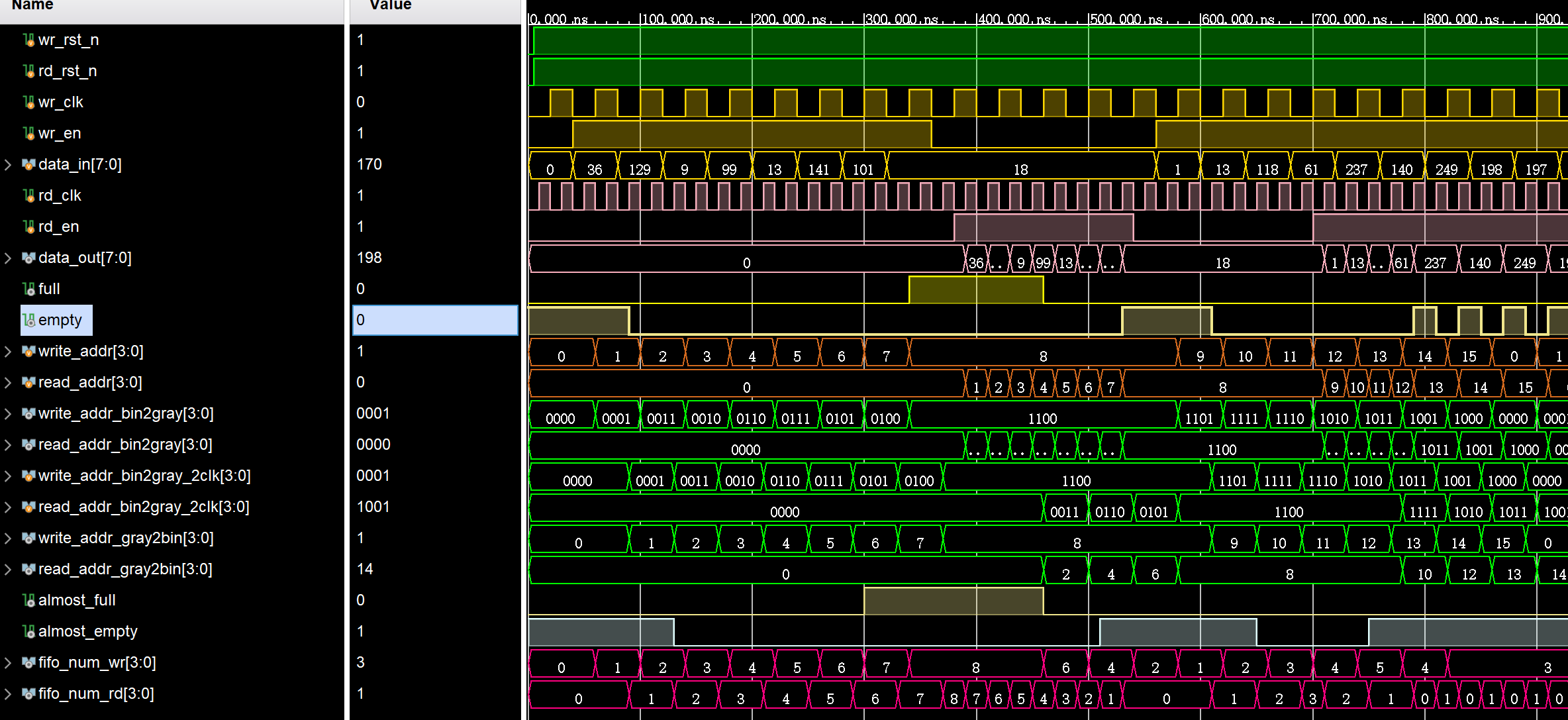
3.异步FIFO
1 | module async_fifo_test #( |
- 仿真结果:
4.FIFO深度计算
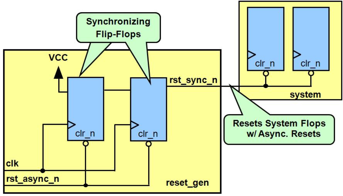
5.异步复位同步释放
电路结构如下:
1
2
3
4
5
6
7
8
9
10
11always @ (posedge clk, negedge rst_async_n)
if (!rst_async_n) begin
rst_s1 <= 1'b0;
rst_s2 <= 1'b0;
end
else begin
rst_s1 <= 1'b1;
rst_s2 <= rst_s1;
end
assign rst_sync_n = rst_s2;
存储相关
1.ROM
1 | module single_port_rom #( //read only |
2.单端口RAM
1 | module single_port_ram #( |
3.伪双端口RAM
1 | module single_dual_ram #( |
时钟切换电路
这里直接做的是异步时钟的切换电路
1
2
3
4
5
6
7
8
9
10
11
12
13
14
15
16
17
18
19
20
21
22
23
24
25
26
27
28
29
30
31
32
33
34
35
36
37
38
39
40
41
42
43
44
45
46
47
48
49
50
51
52
53
54
55
56
57
58
59
60
61
62
63
64
65
66
67
68module clk_change(
input clka ,
input clkb ,
input rst_n ,
input select ,
output outclk
);
//A域相关参数
reg pos_reg1_A;
reg pos_reg2_A;
reg neg_reg_A;
//B域相关参数
reg pos_reg1_B;
reg pos_reg2_B;
reg neg_reg_B;
//在A时钟域下
//1.同步B域的寄存器输出
always @(posedge clka or negedge rst_n) begin
if(~rst_n) begin
pos_reg1_A <= 'd0;
pos_reg2_A <= 'd0;
end
else begin
pos_reg1_A <= (~neg_reg_B) & select;
pos_reg2_A <= pos_reg1_A;
end
end
//2.下降沿寄存
always @(negedge clka or negedge rst_n) begin
if(~rst_n) begin
neg_reg_A <= 'd0;
end
else begin
neg_reg_A <= pos_reg2_A;
end
end
//在B时钟域下
//1.同步A域的寄存器输出
always @(posedge clkb or negedge rst_n) begin
if(~rst_n) begin
pos_reg1_B <= 'd0;
pos_reg2_B <= 'd0;
end
else begin
pos_reg1_B <= (~neg_reg_A) & select;
pos_reg2_B <= pos_reg1_B;
end
end
//2.下降沿寄存
always @(negedge clkb or negedge rst_n) begin
if(~rst_n) begin
neg_reg_B <= 'd0;
end
else begin
neg_reg_B <= pos_reg2_B;
end
end
//结果输出
assign outclk = (neg_reg_A & clka) || (neg_reg_B & clkb);
endmodule这里我觉得关键是为什么要用下降沿触发去锁存一拍select而不是上升沿,手撕代码2 | 无毛刺时钟切换 - 知乎这篇文章里面已经解释得很清楚了,如果用上升沿,那实际电路中,寄存器输出会在时钟上升沿之后晚一点点到达,这晚一点的时钟就可能产生毛刺
频率检测计
参考时钟 50Mhz,检测时钟为 1-200Mhz,写出Verilog来
重点:产生一个门控,在该门控下进行基准时钟与待测时钟的计数,门控的意义是为了保证两个时钟计数的时间是相同的,那么就存在基准时钟周期$\times$基准时钟计数个数=待测时钟周期$\times$待测时钟计数个数的关系,从而得到待测频率。
1
2
3
4
5
6
7
8
9
10
11
12
13
14
15
16
17
18
19
20
21
22
23
24
25
26
27
28
29
30
31
32
33
34
35
36
37
38
39
40
41
42
43
44
45
46
47
48
49
50
51
52
53
54
55
56
57
58
59
60
61
62
63
64
65
66
67
68
69
70
71
72
73
74
75
76
77
78
79
80
81
82
83
84
85
86
87
88
89
90
91
92
93
94
95
96
97
98
99
100
101
102
103
104
105
106module frequency_detect
//========================< 参数 >==========================================
#(
parameter CLK_S_FRE = 31'd50 , // 基准时钟频率值
parameter GATE_TIME = 31'd5000 // 门控时间设置
)
//========================< 端口 >==========================================
(
input clk_s , // 基准时钟信号
input rst_n , // 复位信号
input clk_x , // 被测时钟信号
output reg [31:0] data_x // 被测时钟频率输出
);
//========================< 信号 >==========================================
reg [31:0] gate_cnt ;
reg gate ;
reg gate_s_r1 ;
reg gate_s_r2 ;
reg gate_x_r1 ;
reg gate_x_r2 ;
reg [31:0] s_cnt ;
reg [31:0] s_cnt_r ;
reg [31:0] x_cnt ;
reg [31:0] x_cnt_r ;
wire neg_gate_s ;
wire neg_gate_x ;
//==========================================================================
//== ________________ _______________
//== gate门控 ___| |___| |____
//== gate_cnt 0 1 5000 0 1 5000
//==========================================================================
always @(posedge clk_x or negedge rst_n) begin
if(!rst_n)
gate_cnt <= 'd0;
else if(gate_cnt == GATE_TIME + 20)
gate_cnt <= 'd0;
else
gate_cnt <= gate_cnt + 1'b1;
end
always @(posedge clk_x or negedge rst_n) begin
if(!rst_n)
gate <= 1'b0;
else if(gate_cnt < GATE_TIME)
gate <= 1'b1;
else
gate <= 1'b0;
end
//==========================================================================
//== 打拍检测下降沿
//==========================================================================
always @(posedge clk_s) begin
gate_s_r1 <= gate;
gate_s_r2 <= gate_s_r1;
end
always @(posedge clk_x) begin
gate_x_r1 <= gate;
gate_x_r2 <= gate_x_r1;
end
assign neg_gate_s = gate_s_r2 & (~gate_s_r1);
assign neg_gate_x = gate_x_r2 & (~gate_x_r1);
//==========================================================================
//== 门控下的计数
//==========================================================================
always @(posedge clk_s or negedge rst_n) begin
if(!rst_n) begin
s_cnt <= 'd0; s_cnt_r <= 'd0;
end
else if(neg_gate_s) begin
s_cnt <= 'd0; s_cnt_r <= s_cnt;
end
else if(gate_s_r1) begin
s_cnt <= s_cnt + 1'b1;
end
end
always @(posedge clk_x or negedge rst_n) begin
if(!rst_n) begin
x_cnt <= 'd0; x_cnt_r <= 'd0;
end
else if(neg_gate_x) begin
x_cnt <= 'd0; x_cnt_r <= x_cnt;
end
else if(gate_x_r1) begin
x_cnt <= x_cnt + 1'b1;
end
end
//==========================================================================
//== 输出频率值
//==========================================================================
always @(posedge clk_s or negedge rst_n) begin
if(!rst_n) begin
data_x <= 'd0;
end
else if(~gate_s_r2 & gate_s_r1) begin
data_x <= (CLK_S_FRE * x_cnt_r ) / s_cnt_r;
end
end
endmodule- 仿真结果:
奇偶校验
奇校验:如果数据单元中1的数量已经是奇数,则校验位设置为0;否则,校验位设置为1
偶校验:如果数据单元中1的数量已经是偶数,则校验位设置为0;否则,校验位设置为1
按位异或,结果为1,代表有奇数个1;结果为0,代表有偶数个1
1
2
3
4
5
6
7
8
9
10
11
12
13
14
15
16
17
18
19
20
21
22
23
24
25
26
27
28
29
30
31
32
33
34
35
36
37
38
39
40
41
42module Parity_Check(
input clk ,
input rst_n ,
input in_bit , //输入的比特位
input [7 : 0] in_byte , //输入的字节数
output reg odd_bit , //比特位奇校验输出
output reg even_bit , //比特位偶校验输出
output reg odd_byte , //字节数奇校验输出
output reg even_byte //字节数偶校验输出
);
//对输入的比特位进行奇偶校验
always @(posedge clk or negedge rst_n) begin
if(~rst_n) begin
odd_bit <= 'd1;
even_bit <= 'd0;
end
else begin
if(in_bit) begin
odd_bit <= ~odd_bit;
even_bit <= ~even_bit;
end
else begin
odd_bit <= odd_bit;
even_bit <= even_bit;
end
end
end
//对输出的字节数进行奇偶校验
always @(posedge clk or negedge rst_n) begin
if(~rst_n) begin
odd_byte <= 'd1;
even_byte <= 'd0;
end
else begin
odd_byte <= ~(^in_byte);
even_byte <= ^in_byte;
end
end
endmodule
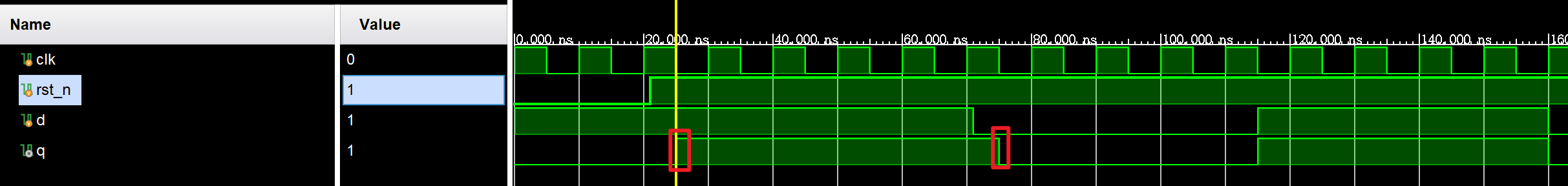
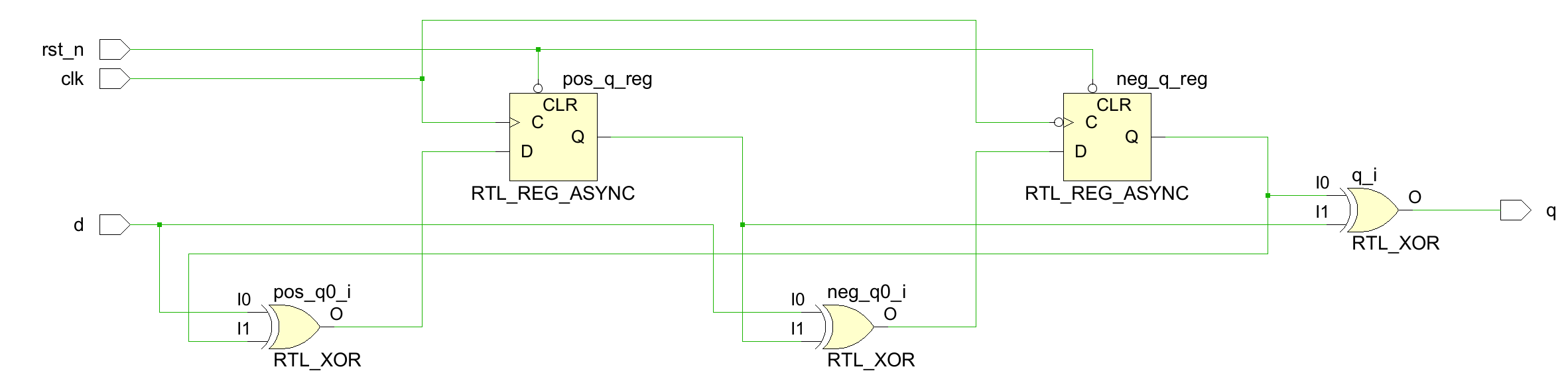
双边沿敏感
实现对时钟上下沿的采样,但是一个信号不能同时在上升沿和下降沿赋值
1
2
3
4
5
6
7
8
9
10
11
12
13
14
15
16
17
18
19
20
21
22
23
24
25
26
27
28
29
30module Double_edge_trigger(
input clk ,
input rst_n,
input d ,
output q
);
reg pos_q, neg_q;
always @(posedge clk or negedge rst_n) begin
if(~rst_n) begin
pos_q <= 'd0;
end
else begin
pos_q <= d ^ neg_q;
end
end
always @(negedge clk or negedge rst_n) begin
if(~rst_n) begin
neg_q <= 'd0;
end
else begin
neg_q <= d ^ pos_q;
end
end
assign q = neg_q ^ pos_q;
endmodule- 仿真结果:
半加器、全加器
半加器:
1
2
3
4
5
6
7
8
9
10
11module half_adder(
input a ,
input b ,
output c ,
output cout //进位
);
assign c = a ^ b;
assign cout = a & b;
endmodule全加器:
1
2
3
4
5
6
7
8
9
10
11
12module full_adder(
input a ,
input b ,
input cin ,
output c ,
output cout
);
assign c = a ^ b ^ c; //有奇数个1的时候结果为1
assign cout = a & b | cin & (a ^ b);
endmodule
查找相关
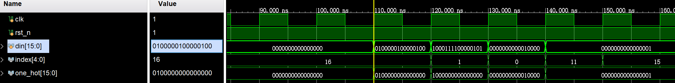
1.寻找第一个1(高位)的位置
与仲裁器中提到的掩码写法很类似
1
2
3
4
5
6
7
8
9
10
11
12
13
14
15
16
17
18
19
20
21
22
23
24
25
26
27
28
29
30
31
32
33
34module Find_First1_index #(
parameter DATA_WIDTH = 16
)(
input clk ,
input rst_n ,
input [DATA_WIDTH - 1 : 0] din ,
output reg [$clog2(DATA_WIDTH) : 0] index
);
wire [DATA_WIDTH - 1 : 0] one_hot;
wire [DATA_WIDTH - 1 : 0] pre_din;
assign pre_din[DATA_WIDTH - 1] = 1'b0;
assign pre_din[DATA_WIDTH - 2 : 0] = pre_din[DATA_WIDTH - 1 : 1] | din[DATA_WIDTH - 1 : 1];
assign one_hot = din & ~pre_din;
//利用(N-$clog2(one_hot)-1)输出最终位置
always @(posedge clk or negedge rst_n) begin
if(~rst_n) begin
index <= 'd16; //表示一个非法值,代表此时没有1
end
else begin
if(one_hot) begin
index <= DATA_WIDTH - $clog2(one_hot) - 1;
end
else begin
index <= 'd16;
end
end
end
endmodule- 仿真结果:
2.寻找最后一个1(低位)的位置
这里可以直接参考仲裁器中补码的写法
1
2
3
4
5
6
7
8
9
10
11
12
13
14
15
16
17
18
19
20
21
22
23
24
25
26
27
28
29module Find_last1_index #(
parameter DATA_WIDTH = 16
)(
input clk ,
input rst_n ,
input [DATA_WIDTH - 1 : 0] din ,
output reg [$clog2(DATA_WIDTH) : 0] index
);
wire [DATA_WIDTH - 1 : 0] one_hot;
assign one_hot = din & (~(din - 1));
//利用(N-$clog2(one_hot)-1)输出最终位置
always @(posedge clk or negedge rst_n) begin
if(~rst_n) begin
index <= 'd16; //表示一个非法值,代表此时没有1
end
else begin
if(one_hot) begin
index <= DATA_WIDTH - $clog2(one_hot) - 1;
end
else begin
index <= 'd16;
end
end
end
endmodule- 仿真结果: