0%

FPGA数字信号处理之常用通信接口时序

本节包括SPI配置DAC芯片实例、异步并口通信等。

SPI配置时序

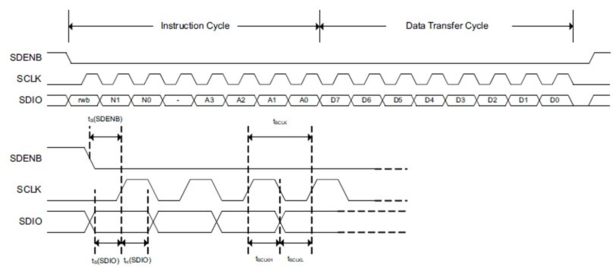
1.某DAC芯片的SPI配置时序

  • 此时时序的关键是:时钟上升沿主机给从机发数据,时钟下降沿从机给主机发数据
image-20240315133651049
  • 正因如此,利用FPGA的系统时钟产生SPI的分频时钟后,需要进行180°时钟反相,也就是用产生的分频时钟去控制SPI的配置时序,但最终输出的SPI实际时钟是分频时钟的180°反相,这样能使得SPI上要发送的数据正好处于SPI时钟的上升沿

    image-20240315134559957
  • 并且,关于DAC的配置,总共需要发送32个16bit的数据才算完成,此处牵扯到串行处理,故用状态机控制
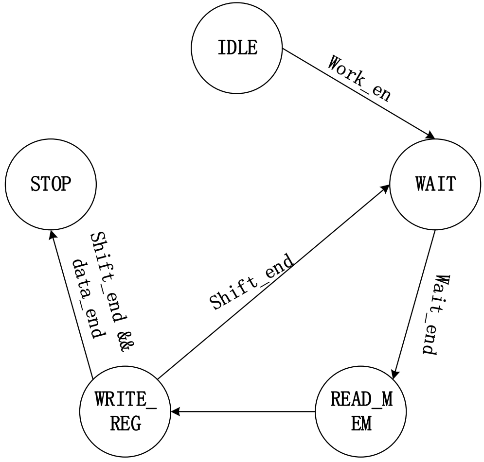
    image-20240315134814666

2.源代码

1
2
3
4
5
6
7
8
9
10
11
12
13
14
15
16
17
18
19
20
21
22
23
24
25
26
27
28
29
30
31
32
33
34
35
36
37
38
39
40
41
42
43
44
45
46
47
48
49
50
51
52
53
54
55
56
57
58
59
60
61
62
63
64
65
66
67
68
69
70
71
72
73
74
75
76
77
78
79
80
81
82
83
84
85
86
87
88
89
90
91
92
93
94
95
96
97
98
99
100
101
102
103
104
105
106
107
108
109
110
111
112
113
114
115
116
117
118
119
120
121
122
123
124
125
126
127
128
129
130
131
132
133
134
135
136
137
138
139
140
141
142
143
144
145
146
147
148
149
150
151
152
153
154
155
156
157
158
159
160
161
`timescale 1ns / 1ps

module spi_ctrl(
input wire sclk,//系统时钟50Mhz
input wire rst_n,
input wire work_en,//触发配置操作的使能
output reg conf_end,
output wire spi_clk,//50-60mhz
output wire spi_sdi,
output wire spi_csn,
input wire spi_sdo//读输入管脚不进行编程
);

parameter IDLE = 5'b0_0001;
parameter WAIT = 5'b0_0010;
parameter R_MEM= 5'b0_0100;
parameter W_REG= 5'b0_1000;
parameter STOP = 5'b1_0000;

parameter H_DIV_CYC = 5'd25-1;

reg [4:0] state;//状态机的寄存器变量,编码方式采用独热码
reg [4:0] div_cnt;
reg clk_p=1'b0;
wire clk_n;
reg pose_flag;
reg [3:0] wait_cnt;
reg [3:0] shift_cnt;
reg [4:0] r_addr;
wire [15:0] r_data;
wire wren;
reg [15:0] shift_buf;
reg data_end;
reg sdi;
reg csn;
reg tck;

//分频计数器
always @(posedge sclk or negedge rst_n)
if(rst_n == 1'b0)
div_cnt <= 5'd0;
else if( div_cnt == H_DIV_CYC )
div_cnt <= 'd0;
else
div_cnt <= div_cnt + 1'b1;
//分频时钟不允许做寄存器的触发时钟,也就是不能卸载always块的触发列表中
always @(posedge sclk or negedge rst_n)
if(rst_n == 1'b0)
clk_p <= 1'b0;
else if(div_cnt == H_DIV_CYC)
clk_p <= ~clk_p;

assign clk_n=~clk_p;

always @(posedge sclk or negedge rst_n)
if(rst_n == 1'b0)
pose_flag <= 1'b0;
else if(clk_p == 1'b0 && div_cnt == H_DIV_CYC)
pose_flag <= 1'b1;
else pose_flag <= 1'b0;

always @(posedge sclk or negedge rst_n)
if(rst_n == 1'b0)
wait_cnt <= 'd0;
else if(state == WAIT && pose_flag == 1'b1)
wait_cnt <= wait_cnt + 1'b1;
else if(state != WAIT)
wait_cnt <= 4'd0;

//fsm
always @(posedge sclk or negedge rst_n)
if(rst_n == 1'b0)
state <= IDLE;
else case (state)
IDLE :if(work_en == 1'b1)
state <= WAIT;
WAIT :if(wait_cnt[3] == 1'b1)
state <= R_MEM;
R_MEM: state <=W_REG;
W_REG: if(shift_cnt == 4'd15 && pose_flag == 1'b1 && data_end != 1'b1)
state <= WAIT;
else if(shift_cnt == 4'd15 && pose_flag == 1'b1 && data_end == 1'b1)
state <= STOP;
STOP: state <= STOP;
default : state <= IDLE;
endcase

always @(posedge sclk or negedge rst_n)
if(rst_n == 1'b0)
shift_cnt <= 'd0;
else if(state == W_REG && pose_flag == 1'b1)
shift_cnt <= shift_cnt + 1'b1;
else if( state != W_REG)
shift_cnt <= 4'd0;

//读mem的地址产生
always @(posedge sclk or negedge rst_n)
if(rst_n == 1'b0)
r_addr <= 'd0;
else if(state == R_MEM)
r_addr <= r_addr + 1'b1;

//data_end 最后一个需要移位数据
always @(posedge sclk or negedge rst_n)
if(rst_n == 1'b0)
data_end <= 1'b0;
else if(state == R_MEM && (&r_addr) == 1'b1)//等效于r_addr == 5'd31
data_end <= 1'b1;

assign wren =1'b0;

always @(posedge sclk or negedge rst_n)
if(rst_n == 1'b0)
shift_buf<='d0;
else if(state == R_MEM)
shift_buf <= r_data;
else if(state == W_REG && pose_flag == 1'b1)
shift_buf <= {shift_buf[14:0],1'b1};

//数据的输出
always @(posedge sclk or negedge rst_n)
if(rst_n == 1'b0)
sdi<=1'b0;
else if(state == W_REG)
sdi<=shift_buf[15];
else
sdi <= 1'b0;

always @(posedge sclk or negedge rst_n)
if(rst_n == 1'b0)
csn <= 1'b1;
else if(state == W_REG)
csn <= 1'b0;
else
csn <= 1'b1;

always @(posedge sclk or negedge rst_n)
if(rst_n == 1'b0)
tck<=1'b0;
else if(state == W_REG )
tck<=clk_n;
else
tck<=1'b0;

assign spi_clk = tck;
assign spi_csn = csn;
assign spi_sdi = sdi;

always @(posedge sclk or negedge rst_n)
if(rst_n == 1'b0)
conf_end <= 1'b0;
else if(state == STOP)
conf_end <= 1'b1;

blk_mem_gen_0 ram_16x32_sr_inst (
.addra ( r_addr ),//读地址
.clka ( sclk ),
.douta ( r_data ) //读数据
);

endmodule

3.Testbench

1
2
3
4
5
6
7
8
9
10
11
12
13
14
15
16
17
18
19
20
21
22
23
24
25
26
27
28
29
30
31
32
33
34
35
36
37
38
39
40
41
42
43
44
45
46
47
48
49
50
51
52
53
54
55
56
57
58
59
60
61
`timescale 1ns / 1ps

module dac_spi_tb;

reg sclk,rst_n;
reg work_en;
wire spi_clk,sclk_csn,spi_sdi;
reg [15:0] send_mem [31:0];
reg [15:0] shift_buf;

initial begin
rst_n =0;
sclk =0;
#100;
rst_n =1;
end

initial begin
work_en =0;
#150
work_en =1;
end

initial begin
$readmemb("D:\\App_Data_File\\Vivado_data\\Vivado_project\\DSP_design\\DAC_SPI\\dac_ini_16x32.mif",send_mem);
end

always #10 sclk = ~sclk;

initial begin
rec_spi();
end

spi_ctrl spi_ctrl_inst(
.sclk (sclk),//系统时钟50Mhz
.rst_n (rst_n),
.work_en (work_en),//触发配置操作的使能
.conf_end (conf_end),
.spi_clk (spi_clk),//50-60mhz
.spi_sdi (spi_sdi),
.spi_csn (spi_csn),
.spi_sdo ()//读输入管脚不进行编程
);

task rec_spi();
integer i,j;
begin
for (i=0;i<32;i=i+1)begin
for(j=0;j<16;j=j+1)begin
@(posedge spi_clk);
shift_buf = {shift_buf[14:0],spi_sdi};
if(j==15 && shift_buf == send_mem[i])
$display("ok data index is %d rec_d=%d send_d=%d",i,shift_buf,send_mem[i]);
else if(j== 15)
$display("error");
end
end
end
endtask

endmodule
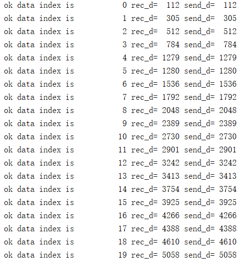
  • 结果如下:

    image-20240315135211882
  • 这里写测试代码的方式值得一学,不然还得人工判断传输的结果是否正确

    1
    2
    3
    4
    5
    6
    7
    8
    9
    10
    11
    12
    13
    14
    15
    task rec_spi();
    integer i,j;
    begin
    for (i=0;i<32;i=i+1)begin
    for(j=0;j<16;j=j+1)begin
    @(posedge spi_clk);
    shift_buf = {shift_buf[14:0],spi_sdi};
    if(j==15 && shift_buf == send_mem[i])
    $display("ok data index is %d rec_d=%d send_d=%d",i,shift_buf,send_mem[i]);
    else if(j== 15)
    $display("error");
    end
    end
    end
    endtask

4.Reference


异步并口通信

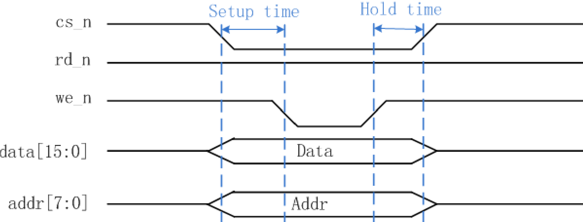
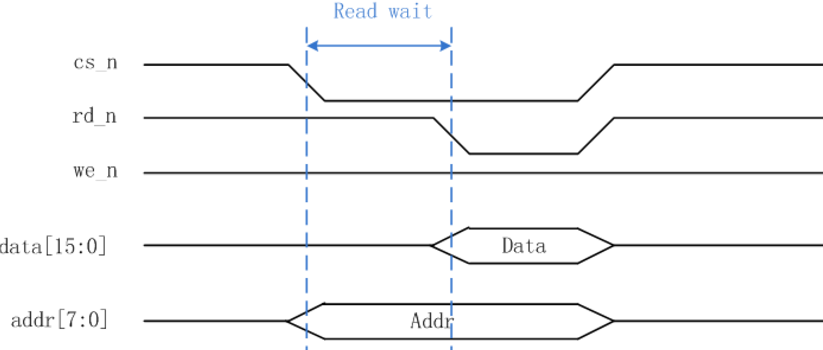
  • 异步并口应用:CPU类的芯片与FPGA的数据交互,数据速率一般在100Mbps以内,数据总线不大于16bit

  • 写操作(外部芯片对FPGA写)的时序图:

    image-20240322155750268
  • 读操作(外部芯片读FPGA内数据)时序图:

image-20240322160016934

1.源代码

1
2
3
4
5
6
7
8
9
10
11
12
13
14
15
16
17
18
19
20
21
22
23
24
25
26
27
28
29
30
31
32
33
34
35
36
37
38
39
40
41
42
43
44
45
46
47
48
49
50
51
52
53
54
55
56
57
58
59
60
61
62
63
64
65
66
67
68
`timescale 1ns / 1ps

module asyn_parallel(
input clk,
input rst_n,
input cs_n,
input we_n,
input rd_n,
input [7:0] addr,
inout [15:0] data
);

reg [15:0] rom_data[7:0]; //FPGA内部存储

//降低亚稳态出现的概率把CS_n rd_n we_n;单比特信号打两拍
reg [1:0] cs_n_2bit, rd_n_2bit, we_n_2bit;
always @(posedge clk or negedge rst_n) begin
if(~rst_n) begin
{cs_n_2bit, rd_n_2bit, we_n_2bit} <= {2'b11, 2'b11, 3'b11};
end
else begin
{cs_n_2bit, rd_n_2bit, we_n_2bit} <= {{cs_n_2bit[0], cs_n}, {rd_n_2bit[0], rd_n}, {we_n_2bit[0], we_n}};
end
end
//同样,对输入的地址和数据也打两拍
reg [15:0] addr_2clk;
reg [31:0] data_2clk;
always @(posedge clk or negedge rst_n) begin
if(~rst_n) begin
{addr_2clk, data_2clk} <= {16'b0, 32'b0};
end
else begin
{addr_2clk, data_2clk} <= {{addr_2clk[7:0], addr}, {data_2clk[15:0], data}};
end
end

//三态门
reg [15:0] data_r;
assign data = (cs_n_2bit[1] == 0 && we_n == 1'b1 && rd_n_2bit[1] == 1'b0) ? data_r : 16'hzzzz; //当读拉低时,将数据输出给外部设备

//读时序:外部设备读FPGA
always @(posedge clk or negedge rst_n) begin
if(~rst_n) begin
data_r <= 16'd0;
end
else if(cs_n_2bit[1] == 1'b0) begin
if(we_n_2bit[1] == 1'b1) begin //在写拉高时,先把要读的数的地址获得,提前知道要读哪个数
data_r <= rom_data[addr_2clk[15:8]];
end
end
end

//写时序:外部设备对FPGA写
integer i;
always @(posedge clk or negedge rst_n) begin
if(~rst_n) begin
for(i = 0; i < 8; i = i + 1) begin
rom_data[i] <= 16'd0;
end
end
else if(cs_n_2bit[1] == 1'b0) begin
if(rd_n_2bit[1] == 1'b1 && we_n_2bit[1] == 1'b0) begin
rom_data[addr_2clk[15:8]] <= data_2clk[31:16];
end
end
end

endmodule

2.Testbench*

  • testbench的测试方式值得学习,其实就根据时序图给出每个时序信号就可
1
2
3
4
5
6
7
8
9
10
11
12
13
14
15
16
17
18
19
20
21
22
23
24
25
26
27
28
29
30
31
32
33
34
35
36
37
38
39
40
41
42
43
44
45
46
47
48
49
50
51
52
53
54
55
56
57
58
59
60
61
62
63
64
65
66
67
68
69
70
71
72
73
74
75
76
77
78
79
80
81
82
83
84
85
86
87
88
89
90
91
92
93
94
95
96
97
98
99
100
101
102
103
104
105
106
107
108
109
110
111
112
113
114
115
116
117
118
119
120
121
122
123
124
125
126
`timescale 1ns / 1ps

module asyn_parallel_tb;

parameter setup_time=2;
parameter hold_time=2;
parameter data_time=4;
parameter read_wait=5;

reg sclk, rst_n;
reg cs_n, rd_n, wr_n;
reg [15:0] data;
reg [7:0] addr;
wire [15:0] w_data;

initial begin
sclk =0;
rst_n =0;
#200
rst_n =1;
end

initial begin
cs_n=1;
rd_n=1;
wr_n=1;
data=0;
addr=0;

#300;
write_data(8);
#100;
read_data(8);
end

always #10 sclk = ~sclk;
//测试激励的三态门
assign w_data = (wr_n==1'b0) ? data : 16'hzzzz;
//写数据的任务
task write_data(input [3:0] len);
integer i;
begin
for(i=0; i<len; i=i+1)
begin
cs_n=0;
data=i[15:0];
addr=i[7:0];
setup_dly();
wr_n=0;
data_dly();
$display("write data addr is %d = %d",i,w_data);
wr_n=1;
hold_dly();
//cs_n=1;
end
cs_n =1;
end
endtask
task read_data(input [3:0] len);
integer i;
begin
for(i=0; i<len; i=i+1)
begin
cs_n=0;
addr=i[7:0];
read_dly();
rd_n=0;
data_dly();
$display("read data addr is %d = %d",i,w_data);
rd_n=1;
end
cs_n =1;
end
endtask

asyn_parallel parall_interf_inst(
.clk (sclk),//50mhz
.rst_n (rst_n),
.cs_n (cs_n),
.rd_n (rd_n),
.we_n (wr_n),
.data (w_data),//1Mhz
.addr (addr)
);

//基本的延时任务
task setup_dly();
integer i;
begin
for (i=0;i<setup_time;i=i+1)
begin
@(posedge sclk);
end
end
endtask

task hold_dly();
integer i;
begin
for (i=0;i<hold_time;i=i+1)
begin
@(posedge sclk);
end
end
endtask

task data_dly();
integer i;
begin
for (i=0;i<data_time;i=i+1)
begin
@(posedge sclk);
end
end
endtask
task read_dly();
integer i;
begin
for (i=0;i<read_wait;i=i+1)
begin
@(posedge sclk);
end
end
endtask

endmodule
  • 仿真结果:

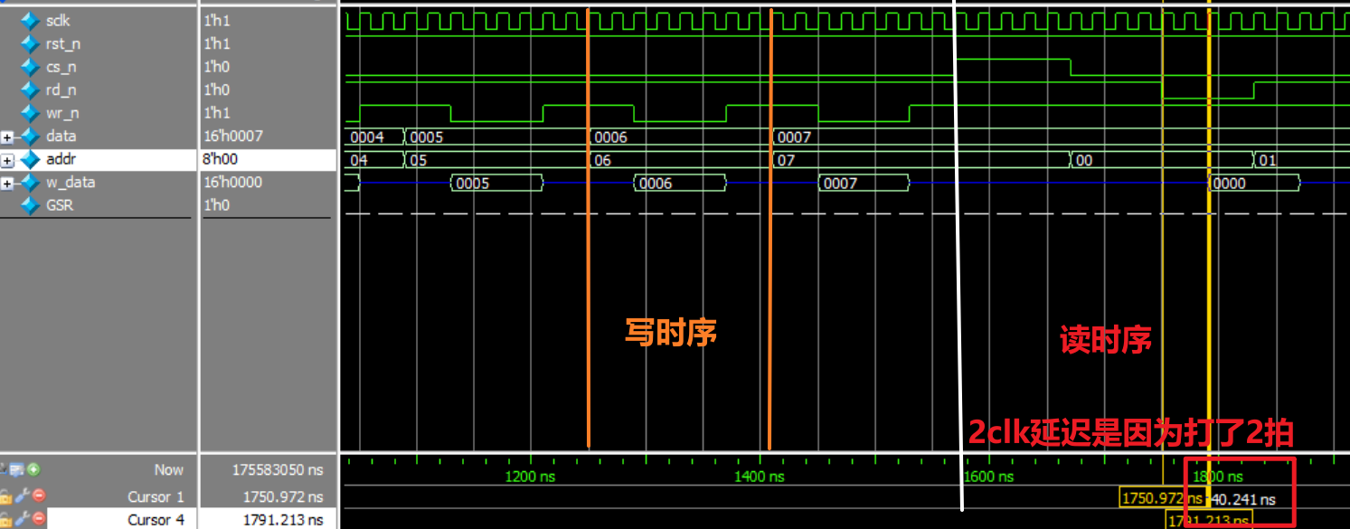
    image-20240322161832106

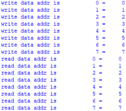
    image-20240322161921263

3.Reference


欢迎来到ssy的世界