本文主要对牛客网Verilog刷题中的进阶习题进行记录。
输入序列连续的序列检测
请编写一个序列检测模块,检测输入信号a是否满足01110001序列,当信号满足该序列,给出指示信号match。

sequence_detect_easy.v
1
2
3
4
5
6
7
8
9
10
11
12
13
14
15
16
17
18
19
20
21
22
23
24
25
26
27
28
29
30
31
32
33
34
35
36
37
38
39
40
41
42
43
44
45
46
47
48
49
50
51
52
53
54
55
56
57
58
59
60
61
62
63
64
65
66
67
68
69
70
71
72
73
74
75
76
77
78
79
80
81
82
83
84
85
86
87
88
89
90
91
92
93
94
module sequence_detect_easy(
input clk,
input rst_n,
input a,
output reg match
);
//状态定义
parameter IDLE = 4'd0, //初始状态
S1 = 4'd1, //"0"
S2 = 4'd2, //"01"
S3 = 4'd3, //"011"
S4 = 4'd4, //"0111"
S5 = 4'd5, //"01110"
S6 = 4'd6, //"011100"
S7 = 4'd7, //"0111000"
S8 = 4'd8; //"01110001"
reg [3:0] state,next_state;
//状态跳转
always @(posedge clk or negedge rst_n) begin
if(~rst_n) begin
state <= IDLE;
end
else begin
state <= next_state;
end
end
//次态判断
always @(*) begin
case (state)
IDLE: next_state = a ? IDLE : S1;
S1: next_state = a ? S2 : S1;
S2: next_state = a ? S3 : S1;
S3: next_state = a ? S4 : S1;
S4: next_state = a ? IDLE : S5;
S5: next_state = a ? S2 : S6;
S6: next_state = a ? S2 : S7;
S7: next_state = a ? S8 : S1;
S8: next_state = a ? S3 : S1; //这里实际上重复检测了,重复的是“011”
default: next_state = IDLE; //本来想省略一个状态的,但若省略S8,那么输出会提前一个clk输出,且不能重复检测
endcase
end
//输出时序
always @(posedge clk or negedge rst_n) begin
if(~rst_n) begin
match <= 1'b0;
end
else begin
match <= (state == S8) ? 1 : 0;
end
end
endmodule
/*使用移位寄存器实现序列检测器会更简单
`timescale 1ns/1ns
module sequence_detect(
input clk,
input rst_n,
input a,
output reg match
);
reg [7:0] a_tem;
always @(posedge clk or negedge rst_n)
if (!rst_n)
begin
match <= 1'b0;
end
else if (a_tem == 8'b0111_0001)
begin
match <= 1'b1;
end
else
begin
match <= 1'b0;
end
always @(posedge clk or negedge rst_n)
if (!rst_n)
begin
a_tem <= 8'b0;
end
else
begin
a_tem <= {a_tem[6:0],a};
end
endmodule
*/
含有无关项的序列检测*
请编写一个序列检测模块,检测输入信号a是否满足011XXX110序列(长度为9位数据,前三位是011,后三位是110,中间三位不做要求),当信号满足该序列,给出指示信号match。
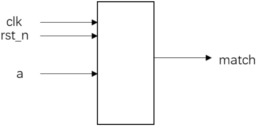
该题使用移位寄存器可以很好的实现
源代码
1
2
3
4
5
6
7
8
9
10
11
12
13
14
15
16
17
18
19
20
21
22
23
24
25
26
27
28
29
30
31
32
33
34
35
module sequence_detect(
input clk,
input rst_n,
input a,
output reg match
);
reg [8 : 0] a_shift_reg;
//移位寄存器
always @(posedge clk or negedge rst_n) begin
if(~rst_n) begin
a_shift_reg <= 9'd0;
end
else begin
a_shift_reg <= {a_shift_reg[7 : 0], a};
end
end
//match判断
always @(posedge clk or negedge rst_n) begin
if(~rst_n) begin
match <= 1'b0;
end
else begin
if(a_shift_reg[8 -: 3] == 3'b011 && a_shift_reg[0 +: 3] == 3'b110) begin
match <= 1'b1;
end
else begin
match <= 1'b0;
end
end
end
endmodule
不重复序列检测*
请编写一个序列检测模块,检测输入信号(a)是否满足011100序列, 要求以每六个输入为一组,不检测重复序列,例如第一位数据不符合,则不考虑后五位。一直到第七位数据即下一组信号的第一位开始检测。当信号满足该序列,给出指示信号match。当不满足时给出指示信号not_match。
模块的接口信号图如下:(要求必须用状态机实现)
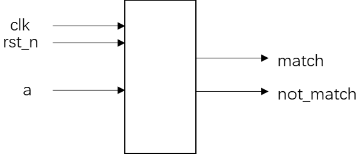
添加一个ERROR状态,当出现某位出现错误是,不再检测后面的位,只是等待这组数据的结束
源代码:
1
2
3
4
5
6
7
8
9
10
11
12
13
14
15
16
17
18
19
20
21
22
23
24
25
26
27
28
29
30
31
32
33
34
35
36
37
38
39
40
41
42
43
44
45
46
47
48
49
50
51
52
53
54
55
56
57
58
59
60
61
62
63
64
65
66
67
68
69
70
71
72
73
74
75
76
77
78
79
80
81
82
83
84
85
86
87
88
89
90
91
92
93
94
95
96
97
98
99
100
101
102
103
104
105
106
107
108
109
110
111
112
113
114
115
116
117
118
119
120
121
122
123
124
125
126
127
128
129
130
131
132
133
134
135
136
137
138
139
140
141
142
143
module Sequence_detect_no_repeat(
input clk,
input rst_n,
input data,
output reg match,
output reg not_match
);
//===============================参数定义=========================
//状态定义
localparam IDLE = 4'd0,
S1 = 4'd1,
S2 = 4'd2,
S3 = 4'd3,
S4 = 4'd4,
S5 = 4'd5,
ERROR = 4'd7;
//现态与次态的定义
reg [3 : 0] cur_state, next_state;
//计数器
reg [2 : 0] counter;
//===============================状态机逻辑=========================
//计数器逻辑
always @(posedge clk or negedge rst_n) begin
if(~rst_n) begin
counter <= 'd0;
end
else begin
if(counter == 5) begin
counter <= 'd0;
end
else begin
counter <= counter + 1;
end
end
end
//1.状态转移
always @(posedge clk or negedge rst_n) begin
if(~rst_n) begin
cur_state <= IDLE;
end
else begin
cur_state <= next_state;
end
end
//2.次态判断
always @(*) begin
next_state = IDLE;
case(cur_state)
IDLE: begin
if(data == 1'b0) begin
next_state = S1;
end
else begin
next_state = ERROR;
end
end
S1: begin
if(data == 1'b1) begin
next_state = S2;
end
else begin
next_state = ERROR;
end
end
S2: begin
if(data == 1'b1) begin
next_state = S3;
end
else begin
next_state = ERROR;
end
end
S3: begin
if(data == 1'b1) begin
next_state = S4;
end
else begin
next_state = ERROR;
end
end
S4: begin
if(data == 1'b0) begin
next_state = S5;
end
else begin
next_state = ERROR;
end
end
S5: begin
if(data == 1'b0) begin
next_state = IDLE;
end
else begin
next_state = ERROR;
end
end
ERROR: begin
if(counter == 5) begin
next_state = IDLE;
end
else begin
next_state = ERROR;
end
end
endcase
end
//3.输出逻辑
always @(posedge clk or negedge rst_n) begin
if(~rst_n) begin
match <= 1'b0;
end
else begin
if(cur_state == S5 && data == 1'b0) begin
match <= 1'b1;
end
else begin
match <= 1'b0;
end
end
end
always @(posedge clk or negedge rst_n) begin
if(~rst_n) begin
not_match <= 1'b0;
end
else begin
if(cur_state == ERROR && counter == 'd5) begin
not_match <= 1'b1;
end
else begin
not_match <= 1'b0;
end
end
end
endmodule
输入序列不连续的序列检测*
请编写一个序列检测模块,输入信号端口为data,表示数据有效的指示信号端口为data_valid。当data_valid信号为高时,表示此刻的输入信号data有效,参与序列检测;当data_valid为低时,data无效,抛弃该时刻的输入。当输入序列的有效信号满足0110时,拉高序列匹配信号match。(要求用状态机实现)
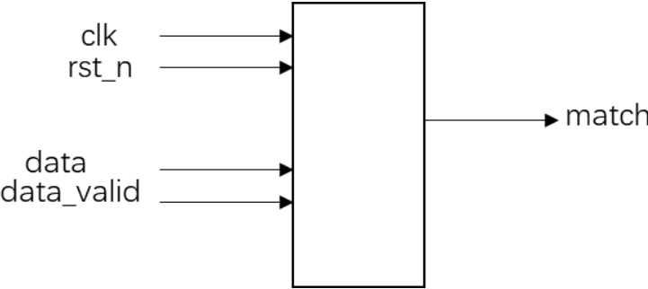
注意判断输出时,由于S3只是011,所以还需对此时输入data(且有效)判断:
cur_state == S3 && data == 1'b0 && data_valid == 1'b1源代码:
1
2
3
4
5
6
7
8
9
10
11
12
13
14
15
16
17
18
19
20
21
22
23
24
25
26
27
28
29
30
31
32
33
34
35
36
37
38
39
40
41
42
43
44
45
46
47
48
49
50
51
52
53
54
55
56
57
58
59
60
61
62
63
64
65
66
67
68
69
70
71
72
73
74
75
76
77
78
79
80
81
82
83
84
module Sequence_detect_Discontinuous(
input clk,
input rst_n,
input data,
input data_valid,
output reg match
);
//===============================参数定义=========================
//状态定义
localparam IDLE = 2'd0,
S1 = 2'd1,
S2 = 2'd2,
S3 = 2'd3;
//现态与次态定义
reg [1 : 0] cur_state, next_state;
//===============================状态机逻辑=========================
//1.状态转移
always @(posedge clk or negedge rst_n) begin
if(~rst_n) begin
cur_state <= IDLE;
end
else begin
cur_state <= next_state;
end
end
//2.次态判断
always @(*) begin
next_state = IDLE;
case(cur_state)
IDLE: begin
if(data_valid && data == 1'b0) begin
next_state = S1;
end
else begin
next_state = IDLE;
end
end
S1: begin
if(data_valid && data == 1'b1) begin
next_state = S2;
end
else begin
next_state = S1;
end
end
S2: begin
if(data_valid && data == 1'b1) begin
next_state = S3;
end
else begin
next_state = S2;
end
end
S3: begin
if(data_valid && data == 1'b0) begin
next_state = IDLE;
end
else begin
next_state = S3;
end
end
endcase
end
//3.输出逻辑
always @(posedge clk or negedge rst_n) begin
if(~rst_n) begin
match <= 1'b0;
end
else begin
if(cur_state == S3 && data == 1'b0 && data_valid == 1'b1) begin
match <= 1'b1;
end
else begin
match <= 1'b0;
end
end
end
endmodule
信号发生器*
请编写一个信号发生器模块,根据波形选择信号wave_choise发出相应的波形:wave_choice=0时,发出方波信号;wave_choice=1时,发出锯齿波信号;wave_choice=2时,发出三角波信号。
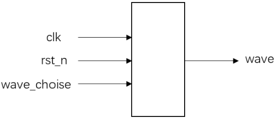
注意
square_wave_cnt < 'd10(1~10、11~19~0)与square_wave_cnt < 'd9 || square_wave_cnt == 'd19(0~9、9~19)的区别。正常来说都是50%占空比的方波,不知为何不加就会牛客网编译器就会报错square_wave_cnt < ‘d10:

square_wave_cnt < ‘d9 || square_wave_cnt == ‘d19

源代码
1
2
3
4
5
6
7
8
9
10
11
12
13
14
15
16
17
18
19
20
21
22
23
24
25
26
27
28
29
30
31
32
33
34
35
36
37
38
39
40
41
42
43
44
45
46
47
48
49
50
51
52
53
54
55
56
57
58
59
60
61
62
63
64
65
66
67
68
69
70
71
72
73
74
75
76
77
78
79
80
81
82
83
84
85
86
87
88
89
90
module signal_generator(
input clk,
input rst_n,
input [1:0] wave_choise,
output reg [4:0]wave
);
//方波计数器
reg [4 : 0] square_wave_cnt;
always @(posedge clk or negedge rst_n) begin
if(~rst_n) begin
square_wave_cnt <= 'd0;
end
else begin
if(wave_choise == 'd0) begin
if(square_wave_cnt == 'd19) begin
square_wave_cnt <= 'd0;
end
else begin
square_wave_cnt <= square_wave_cnt + 1;
end
end
else begin
square_wave_cnt <= 'd0;
end
end
end
//三角波控制器
reg triangle_wave_flag; //其中flag=0代表下降,=1代表上升
always @(posedge clk or negedge rst_n) begin
if(~rst_n) begin
triangle_wave_flag <= 1'b0;
end
else begin
if(wave_choise == 'd2) begin
if(wave == 'd1) begin
triangle_wave_flag <= 1'b1;
end
else begin
if(wave == 'd19) begin //其实此时是1~20的wave为上升,21~0的wave为下降
triangle_wave_flag <= 1'b0;
end
end
end
else begin
triangle_wave_flag <= 1'b0;
end
end
end
//输出选择控制
always @(posedge clk or negedge rst_n) begin
if(~rst_n) begin
wave <= 'd0;
end
else begin
case(wave_choise)
2'd0: begin
if(square_wave_cnt < 'd9 || square_wave_cnt == 'd19) begin
wave <= 'd0;
end
else begin
wave <= 'd20;
end
end
2'd1: begin
if(wave == 'd20) begin
wave <= 'd0;
end
else begin
wave <= wave + 1;
end
end
2'd2: begin
if(triangle_wave_flag == 1'b0) begin
wave <= wave - 1;
end
else begin
wave <= wave + 1;
end
end
default: wave <= 'd0;
endcase
end
end
endmodule
数据串转并电路
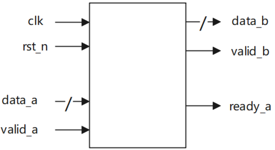
实现串并转换电路,输入端输入单bit数据,每当本模块接收到6个输入数据后,输出端输出拼接后的6bit数据。本模块输入端与上游的采用valid-ready双向握手机制,输出端与下游采用valid-only握手机制。数据拼接时先接收到的数据放到data_b的低位。电路的接口如下图所示。valid_a用来指示数据输入data_a的有效性,valid_b用来指示数据输出data_b的有效性;ready_a用来指示本模块是否准备好接收上游数据,本模块中一直拉高;clk是时钟信号;rst_n是异步复位信号。
源代码:
1
2
3
4
5
6
7
8
9
10
11
12
13
14
15
16
17
18
19
20
21
22
23
24
25
26
27
28
29
30
31
32
33
34
35
36
37
38
39
40
41
42
43
44
45
46
47
48
49
50
51
52
53
54
55
56
57
58
59
60
61
62
63
64
65
66
67
68
69
70
71
72
73
74
75
76
module s_to_p(
input clk ,
input rst_n ,
input valid_a ,
input data_a ,
output reg ready_a ,
output reg valid_b ,
output reg [5:0] data_b
);
reg [5 : 0] data_out_r;
reg [2 : 0] cnt;
always @(posedge clk or negedge rst_n) begin
if(~rst_n) begin
cnt <= 'd0;
end
else begin
if(valid_a && ready_a) begin
if(cnt == 'd5) begin
cnt <= 'd0;
end
else begin
cnt <= cnt + 1;
end
end
end
end
always @(posedge clk or negedge rst_n) begin
if(~rst_n) begin
data_out_r <= 'd0;
end
else begin
if(valid_a) begin
data_out_r <= {data_a, data_out_r[5 : 1]};
end
end
end
always @(posedge clk or negedge rst_n) begin
if(~rst_n) begin
data_b <= 'd0;
end
else begin
if(cnt == 'd5) begin
data_b <= {data_a, data_out_r[5 : 1]};
end
end
end
always @(posedge clk or negedge rst_n) begin
if(~rst_n) begin
ready_a <= 1'b0;
end
else begin
ready_a <= 1'b1;
end
end
always @(posedge clk or negedge rst_n) begin
if(~rst_n) begin
valid_b <= 1'b0;
end
else begin
if(cnt == 'd5) begin
valid_b <= 1'b1;
end
else begin
valid_b <= 1'b0;
end
end
end
endmodule
数据累加输出*
实现串行输入数据累加输出,输入端输入8bit数据,每当模块接收到4个输入数据后,输出端输出4个接收到数据的累加结果。输入端和输出端与上下游的交互采用valid-ready双向握手机制。要求上下游均能满速传输时,数据传输无气泡,不能由于本模块的设计原因产生额外的性能损失。
电路的接口如下图所示。valid_a用来指示数据输入data_in的有效性,valid_b用来指示数据输出data_out的有效性;ready_a用来指示本模块是否准备好接收上游数据,ready_b表示下游是否准备好接收本模块的输出数据;clk是时钟信号;rst_n是异步复位信号。
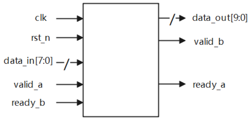
好好理解ready_a和ready_b信号对正常只有valid逻辑的影响,重点看代码里面的注释!
源代码:
1
2
3
4
5
6
7
8
9
10
11
12
13
14
15
16
17
18
19
20
21
22
23
24
25
26
27
28
29
30
31
32
33
34
35
36
37
38
39
40
41
42
43
44
45
46
47
48
49
50
51
52
53
54
55
56
57
58
59
60
61
62
63
64
65
66
67
68
module valid_ready(
input clk ,
input rst_n ,
input [7:0] data_in ,
input valid_a ,
input ready_b ,
output ready_a ,
output reg valid_b ,
output reg [9:0] data_out
);
reg [1 : 0] cnt;
always @(posedge clk or negedge rst_n) begin
if(~rst_n) begin
cnt <= 'd0;
end
else begin
if(valid_a && ready_a) begin //与输出相关的信号时,都带上ready_a就行,因为当本级准备好时,才能正常工作
if(cnt == 'd3) begin
cnt <= 'd0;
end
else begin
cnt <= cnt + 1;
end
end
end
end
//数据输出
always @(posedge clk or negedge rst_n) begin
if(~rst_n) begin
data_out <= 'd0;
end
else begin
if(cnt == 'd0 && valid_a && ready_a && ready_b) begin //这里其实不太好理解,就是当cnt == 0的时候是要开启下一次计算(正常来说),重新加载第一个数据
data_out <= data_in; //如果下一级准备好了,就正常加载,如果没有准备好,数据应该保持,
end
else if(valid_a && ready_a) begin //其实~ready_b成立时,ready_a == 0(根据ready_a的组合逻辑),那么就肯定是data_out保持了
data_out <= data_out + data_in; //所以这里写法可以这样简化,没有单独写出~ready_b的情况
end
end
end
//数据有效信号
always @(posedge clk or negedge rst_n) begin
if(~rst_n) begin
valid_b <= 1'b0;
end
else begin
if(cnt == 'd3 && valid_a && ready_a) begin //这里很容易出错,注意当cnt=='d3时,可不一定是valid_a==1
valid_b <= 1'b1;
end
else begin
if(~ready_b) begin //可以等效成代码:else if(valid_b && ready_b)
valid_b <= valid_b; // valid_b <= 1'd0;
end //该等效代码的理解是:运算完成后需置高1clk,在下一个时钟周期就要归0了
else begin //如果此时下一级准备好了,说明下一级已经读到数据运算有效信号了,就拉低valid_b(就跟没有这个ready信号的正常操作一样)
valid_b <= 1'b0; //如果此时下一级还没有准备好,那么就要继续保持这个valid_b信号,直到下一级在准备好的时候能读到这个信号,知道数据已经运算有效了
end
end //这个我自己写的分支的理解是:运算有效后如果下一级模块还没有准备好(~ready),那么该valid_b信号就要继续保持(因为如果没有准备好,所有输出数据都是要保持的)
end //如果准备好了,那就正常归0(因为正常情况下valid就只会拉高1clk)
end
//输出给上一级的ready
assign ready_a = (valid_b && ~ready_b) ? 0 : 1; //数据有效且下一级未准备好时 输出给上一级的ready拉高
endmodule
非整数倍数据位宽转换24to128*
实现数据位宽转换电路,实现24bit数据输入转换为128bit数据输出。其中,先到的数据应置于输出的高bit位。电路的接口如下图所示。valid_in用来指示数据输入data_in的有效性,valid_out用来指示数据输出data_out的有效性;clk是时钟信号;rst_n是异步复位信号。
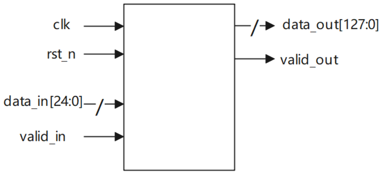
这里的解题思路很巧妙,输入数据是24bit,输出数据是128bit。因为128×3=24×16,所以每输入16个有效数据,就可以产生三个完整的输出。因此设置一个仅在输入数据有效时工作的计数器
cnt,计数范围是0-15。
设置一个数据暂存器
data_lock(128bit),每当输入有效时,将数据从低位移入。每当计数器
cnt计数到5、10、15时,data_out要进行更新,并拉高valid_out一个周期。源代码:
1
2
3
4
5
6
7
8
9
10
11
12
13
14
15
16
17
18
19
20
21
22
23
24
25
26
27
28
29
30
31
32
33
34
35
36
37
38
39
40
41
42
43
44
45
46
47
48
49
50
51
52
53
54
55
56
57
58
59
60
61
62
63
64
65
66
67
68
69
70
71
72
73
74
75
module width_24to128(
input clk ,
input rst_n ,
input valid_in ,
input [23:0] data_in ,
output reg valid_out ,
output reg [127:0] data_out
);
reg [3 : 0] cnt;
reg [127 : 0] data_lock;
//计数器逻辑
always @(posedge clk or negedge rst_n) begin
if(~rst_n) begin
cnt <= 'd0;
end
else begin
if(valid_in) begin
if(cnt == 'd15) begin
cnt <= 'd0;
end
else begin
cnt <= cnt + 1;
end
end
end
end
//移位拼接
always @(posedge clk or negedge rst_n) begin
if(~rst_n) begin
data_lock <= 'd0;
end
else begin
if(valid_in) begin
data_lock <= {data_lock[103 : 0], data_in};
end
end
end
always @(posedge clk or negedge rst_n) begin
if(~rst_n) begin
data_out <= 'd0;
end
else begin
if(cnt == 'd5 && valid_in) begin
data_out <= {data_lock[119 : 0], data_in[23 : 16]}; //在输出这组数据最后一个数的同时,这个数将被存到data_lock中,以便下次使用
end
else if(cnt == 'd10 && valid_in) begin
data_out <= {data_lock[111 : 0], data_in[23 : 8]};
end
else if(cnt == 'd15 && valid_in) begin
data_out <= {data_lock[103 : 0], data_in[23 : 0]};
end
end
end
//输出有效信号
always @(posedge clk or negedge rst_n) begin
if(~rst_n) begin
valid_out <= 1'b0;
end
else begin
if(valid_in && (cnt == 'd5 || cnt == 'd10 || cnt == 'd15)) begin
valid_out <= 1'b1;
end
else begin
valid_out <= 1'b0;
end
end
end
endmodule
非整数倍数据位宽转换8to12
实现数据位宽转换电路,实现8bit数据输入转换为12bit数据输出。其中,先到的数据应置于输出的高bit位。电路的接口如下图所示。valid_in用来指示数据输入data_in的有效性,valid_out用来指示数据输出data_out的有效性;clk是时钟信号;rst_n是异步复位信号。
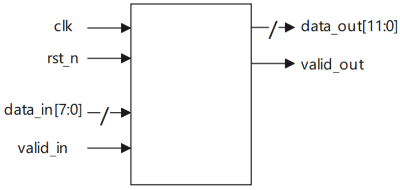
本题解法与上题一致
源代码:
1
2
3
4
5
6
7
8
9
10
11
12
13
14
15
16
17
18
19
20
21
22
23
24
25
26
27
28
29
30
31
32
33
34
35
36
37
38
39
40
41
42
43
44
45
46
47
48
49
50
51
52
53
54
55
56
57
58
59
60
61
62
63
64
65
66
67
68
69
70
71
72
73
module width_8to12(
input clk ,
input rst_n ,
input valid_in ,
input [7:0] data_in ,
output reg valid_out,
output reg [11:0] data_out
);
//8 * 3 = 12 * 2
reg [1 : 0] cnt;
reg [11 : 0] data_lock;
//计数器逻辑
always @(posedge clk or negedge rst_n) begin
if(~rst_n) begin
cnt <= 'd0;
end
else begin
if(valid_in) begin
if(cnt == 'd2) begin
cnt <= 0;
end
else begin
cnt <= cnt + 1;
end
end
end
end
//移位锁存
always @(posedge clk or negedge rst_n) begin
if(~rst_n) begin
data_lock <= 'd0;
end
else begin
if(valid_in) begin
data_lock <= {data_lock[3 : 0], data_in};
end
end
end
always @(posedge clk or negedge rst_n) begin
if(~rst_n) begin
data_out <= 'd0;
end
else begin
if(valid_in && cnt == 'd1) begin
data_out <= {data_lock[7 : 0], data_in[7 : 4]};
end
else if(valid_in && cnt == 'd2) begin
data_out <= {data_lock[3 : 0], data_in};
end
end
end
//数据有效信号
always @(posedge clk or negedge rst_n) begin
if(~rst_n) begin
valid_out <= 1'b0;
end
else begin
if(valid_in && (cnt == 'd1 || cnt == 'd2)) begin
valid_out <= 1'b1;
end
else begin
valid_out <= 1'b0;
end
end
end
endmodule
整数倍数据位宽转换8to16
实现数据位宽转换电路,实现8bit数据输入转换为16bit数据输出。其中,先到的8bit数据应置于输出16bit的高8位。电路的接口如下图所示。valid_in用来指示数据输入data_in的有效性,valid_out用来指示数据输出data_out的有效性;clk是时钟信号;rst_n是异步复位信号。
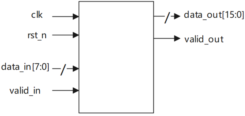
源代码:
1
2
3
4
5
6
7
8
9
10
11
12
13
14
15
16
17
18
19
20
21
22
23
24
25
26
27
28
29
30
31
32
33
34
35
36
37
38
39
40
41
42
43
44
45
46
47
48
49
50
51
52
53
54
55
56
57
58
59
60
61
62
63
64
module width_8to16_integer(
input clk ,
input rst_n ,
input valid_in ,
input [7:0] data_in ,
output reg valid_out ,
output reg [15:0] data_out
);
reg [15 : 0] data_lock;
//8 * 2 = 16
reg cnt;
always @(posedge clk or negedge rst_n) begin
if(~rst_n) begin
cnt <= 'd0;
end
else begin
if(valid_in) begin
cnt <= ~cnt;
end
end
end
//移位输出
always @(posedge clk or negedge rst_n) begin
if(~rst_n) begin
data_lock <='d0;
end
else begin
if(valid_in) begin
data_lock <= {data_lock[7 : 0], data_in};
end
end
end
always @(posedge clk or negedge rst_n) begin
if(~rst_n) begin
data_out <= 'd0;
end
else begin
if(valid_in && cnt == 'd1) begin
data_out <= {data_lock[7 : 0], data_in};
end
end
end
//数据输出有效
always @(posedge clk or negedge rst_n) begin
if(~rst_n) begin
valid_out <= 1'b0;
end
else begin
if(valid_in && cnt == 'd1) begin
valid_out <= 1'b1;
end
else begin
valid_out <= 1'b0;
end
end
end
endmodule
状态机-非重叠的序列检测
设计一个状态机,用来检测序列 10111,要求:
1、进行非重叠检测 即101110111 只会被检测通过一次
2、寄存器输出且同步输出结果(注意rst为低电平复位)
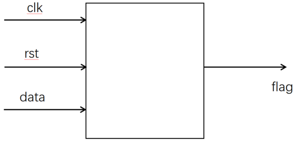
源代码:
1
2
3
4
5
6
7
8
9
10
11
12
13
14
15
16
17
18
19
20
21
22
23
24
25
26
27
28
29
30
31
32
33
34
35
36
37
38
39
40
41
42
43
44
45
46
47
48
49
50
51
52
53
54
55
module sequence_test1(
input wire clk ,
input wire rst ,
input wire data ,
output reg flag
);
//状态定义
localparam IDLE = 3'd0,
S1 = 3'd1,
S2 = 3'd2,
S3 = 3'd3,
S4 = 3'd4;
//现态与次态定义
reg [2 : 0] cur_state, next_state;
//1.状态跳转
always @(posedge clk or negedge rst) begin
if(~rst) begin
cur_state <= IDLE;
end
else begin
cur_state <= next_state;
end
end
//2.次态判断
always @(*) begin
case(cur_state)
IDLE: next_state = data == 1 ? S1 : IDLE;
S1: next_state = data == 0 ? S2 : S1;
S2: next_state = data == 1 ? S3 : S2;
S3: next_state = data == 1 ? S4 : S3;
S4: next_state = data == 1 ? IDLE : S4;
default: next_state = IDLE;
endcase
end
//3.输出判断
always @(posedge clk or negedge rst) begin
if(~rst) begin
flag <= 1'b0;
end
else begin
if(cur_state == S4 && data == 1) begin
flag <= 1'b1;
end
else begin
flag <= 1'b0;
end
end
end
endmodule
状态机-重叠序列检测
设计一个状态机,用来检测序列 1011,要求:
1、进行重叠检测 即10110111 会被检测通过2次
2、寄存器输出,在序列检测完成下一拍输出检测有效(注意rst为低电平复位)
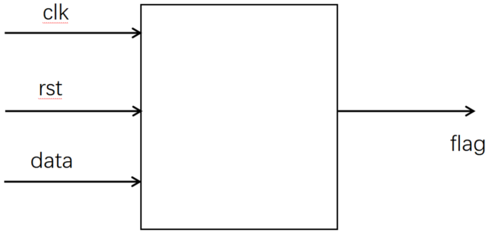
源文件:
1
2
3
4
5
6
7
8
9
10
11
12
13
14
15
16
17
18
19
20
21
22
23
24
25
26
27
28
29
30
31
32
33
34
35
36
37
38
39
40
41
42
43
44
45
46
47
48
49
50
51
52
53
54
55
56
module sequence_test2(
input wire clk ,
input wire rst ,
input wire data ,
output reg flag
);
//*************code***********//
//状态定义
localparam IDLE = 3'd0,
S1 = 3'd1,
S2 = 3'd2,
S3 = 3'd3,
S4 = 3'd4;
//现态与次态定义
reg [2 : 0] cur_state, next_state;
//1.状态跳转
always @(posedge clk or negedge rst) begin
if(~rst) begin
cur_state <= IDLE;
end
else begin
cur_state <= next_state;
end
end
//2.次态判断
always @(*) begin
case(cur_state)
IDLE: next_state = data == 1 ? S1 : IDLE;
S1: next_state = data == 0 ? S2 : S1;
S2: next_state = data == 1 ? S3 : S2;
S3: next_state = data == 1 ? S4 : S3;
S4: next_state = data == 1 ? S1 : S2;
default: next_state = IDLE;
endcase
end
//3.输出判断
always @(posedge clk or negedge rst) begin
if(~rst) begin
flag <= 1'b0;
end
else begin
if(cur_state == S4) begin
flag <= 1'b1;
end
else begin
flag <= 1'b0;
end
end
end
//*************code***********//
endmodule
时钟分频(偶数)*
请使用D触发器设计一个同时输出2/4/8分频的50%占空比的时钟分频。注意rst为低电平复位
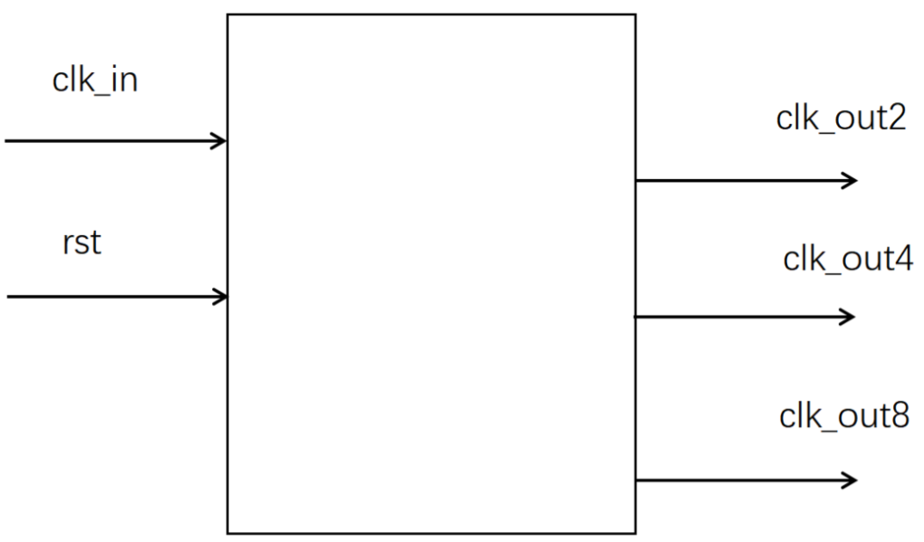
其实偶数分频是有些小技巧的,即利用计数器,不过之前已经会啦
源代码:
1
2
3
4
5
6
7
8
9
10
11
12
13
14
15
16
17
18
19
20
21
22
23
24
25
26
27
28
29
30
31
32
33
34
35
36
37
38
39
40
41
42
module even_div
(
input wire rst ,
input wire clk_in,
output wire clk_out2,
output wire clk_out4,
output wire clk_out8
);
//*************code***********//
reg [2 : 0] clk_reg;
reg clk_out2_r;
reg clk_out4_r;
reg clk_out8_r;
always @(posedge clk_in or negedge rst) begin
if(~rst) begin
clk_reg <= 'd0;
end
else begin
clk_reg <= clk_reg + 1;
end
end
always @(posedge clk_in or negedge rst) begin
if(~rst) begin
clk_out2_r <= 1'b1;
clk_out4_r <= 1'b1;
clk_out8_r <= 1'b1;
end
else begin
clk_out2_r <= clk_reg[0];
clk_out4_r <= clk_reg[1];
clk_out8_r <= clk_reg[2];
end
end
assign clk_out2 = ~clk_out2_r;
assign clk_out4 = ~clk_out4_r;
assign clk_out8 = ~clk_out8_r;
//*************code***********//
endmodule
自动贩售机1**
设计一个自动贩售机,输入货币有三种,为0.5/1/2元,饮料价格是1.5元,要求进行找零,找零只会支付0.5元。
ps:投入的货币会自动经过边沿检测并输出一个在时钟上升沿到1,在下降沿到0的脉冲信号
(d1 0.5元;d2 1元;d3 2元;out1 饮料;out2 零钱)

可以借助该题好好理解米粒(输出取决于当前状态+输入)和摩尔型(输出只取决于当前状态)的区别
- 米粒型由于当前状态与输入有关,可以放在输出逻辑里面判断输出,从而减小状态机数量,但增加输出逻辑的复杂度
- 摩尔型由于当前状态与输出无关,那么其实有很多状态只是为了指示输出,这无形中增加了状态机的数量
米粒型版本:(状态仅表示空闲、累计0.5元、累计1元)
1
2
3
4
5
6
7
8
9
10
11
12
13
14
15
16
17
18
19
20
21
22
23
24
25
26
27
28
29
30
31
32
33
34
35
36
37
38
39
40
41
42
43
44
45
46
47
48
49
50
51
52
53
54
55
56
57
58
59
60
61
62
63
64
65
66
67
68
69
70
71
72
73
74
75
76
77
78
79
80
81
82
83
84
85
86
87
88
89
90
91
92
93
94
95
96
97
98
99
100
101
102
103
104
105
106
107
108
109
110
111
112
113
114
115
116
117
118
119
120
121
122
123
124
125
126
127
128
129
130
131
132
133
134
135
136
137
138
module seller1(
input wire clk ,
input wire rst ,
input wire d1 ,
input wire d2 ,
input wire d3 ,
output reg out1,
output reg [1:0]out2
);
//状态定义
parameter IDLE = 'd0,
S1 = 'd1, //0.5
S2 = 'd2; //1
//现态与次态定义
reg [2 : 0] cur_state, next_state;
//1.状态跳转
always @(posedge clk or negedge rst) begin
if(~rst) begin
cur_state <= IDLE;
end
else begin
cur_state <= next_state;
end
end
//2.次态判断
always @(*) begin
//next_state = IDLE; 因为次态判断中存在next_state = next_state;这样的写法,那么就不能把该语句放在前面,不然每次判断后next_state都只会等于IDLE
case(cur_state) //主要原因在于d1,d2,d3都只拉高半个时钟周期
IDLE: begin
case({d1,d2,d3})
3'b100: next_state = S1;
3'b010: next_state = S2;
3'b001: next_state = IDLE;
default: next_state = next_state;
endcase
end
S1: begin
case({d1,d2,d3})
3'b100: next_state = S2;
3'b010: next_state = IDLE;
3'b001: next_state = IDLE;
default: next_state = next_state;
endcase
end
S2: begin
case({d1,d2,d3})
3'b100: next_state = IDLE;
3'b010: next_state = IDLE;
3'b001: next_state = IDLE;
default: next_state = next_state;
endcase
end
default: next_state = IDLE;
endcase
end
//3.输出逻辑
reg out1_r;
reg [1 : 0] out2_r;
always @(posedge clk or negedge rst) begin
if(~rst) begin
out1_r <= 'd0;
out2_r <= 'd0;
end
else begin
case(cur_state)
IDLE: begin
if({d1,d2,d3} == 3'b001) begin //这里{d1,d2,d3}能被捕获到也是挺神奇的
out1_r <= 1'b1;
out2_r <= 'd1;
end
else begin
out1_r <= 1'b0;
out2_r <= 'd0;
end
end
S1: begin
case({d1,d2,d3})
3'b010: begin
out1_r <= 1'b1;
out2_r <= 'd0;
end
3'b001: begin
out1_r <= 1'b1;
out2_r <= 'd2;
end
default: begin
out1_r <= 1'b0;
out2_r <= 'd0;
end
endcase
end
S2: begin
case({d1,d2,d3})
3'b100: begin
out1_r <= 1'b1;
out2_r <= 'd0;
end
3'b010: begin
out1_r <= 1'b1;
out2_r <= 'd1;
end
3'b001: begin
out1_r <= 1'b1;
out2_r <= 'd3;
end
default: begin
out1_r <= 1'b0;
out2_r <= 'd0;
end
endcase
end
default: begin
out1_r <= 1'b0;
out2_r <= 'd0;
end
endcase
end
end
always @(posedge clk or negedge rst) begin
if(~rst) begin
out1 <= 'd0;
out2 <= 'd0;
end
else begin
out1 <= out1_r;
out2 <= out2_r;
end
end
endmodule摩尔型版本(状态表示可能出现的所有累积钱数):
1
2
3
4
5
6
7
8
9
10
11
12
13
14
15
16
17
18
19
20
21
22
23
24
25
26
27
28
29
30
31
32
33
34
35
36
37
38
39
40
41
42
43
44
45
46
47
48
49
50
51
52
53
54
55
56
57
58
59
60
61
62
63
64
65
66
67
68
69
70
71
72
73
74
75
76
77
78
79
80
81
82
83
84
85
86
87
88
89
90
91
92
93
94
module seller1(
input wire clk ,
input wire rst ,
input wire d1 ,
input wire d2 ,
input wire d3 ,
output reg out1,
output reg [1:0]out2
);
//状态定义
parameter IDLE = 'd0,
S1 = 'd1, //0.5
S2 = 'd2, //1
S3 = 'd3, //1.5
S4 = 'd4, //2
S5 = 'd5, //2.5
S6 = 'd6; //3
//现态与次态定义
reg [2 : 0] cur_state, next_state;
//1.状态跳转
always @(posedge clk or negedge rst) begin
if(~rst) begin
cur_state <= IDLE;
end
else begin
cur_state <= next_state;
end
end
//2.次态判断
always @(*) begin
//next_state = IDLE; 因为次态判断中存在next_state = next_state;这样的写法,那么就不能把该语句放在前面,不然每次判断后next_state都只会等于IDLE
case(cur_state) //主要原因在于d1,d2,d3都只拉高半个时钟周期
IDLE: begin
case({d1,d2,d3})
3'b100: next_state = S1;
3'b010: next_state = S2;
3'b001: next_state = S4;
default: next_state = next_state;
endcase
end
S1: begin
case({d1,d2,d3})
3'b100: next_state = S2;
3'b010: next_state = S3;
3'b001: next_state = S5;
default: next_state = next_state;
endcase
end
S2: begin
case({d1,d2,d3})
3'b100: next_state = S3;
3'b010: next_state = S4;
3'b001: next_state = S6;
default: next_state = next_state;
endcase
end
default: next_state = IDLE;
endcase
end
//3.输出逻辑
always @(posedge clk or negedge rst) begin
if(~rst) begin
out1 <= 'd0;
end
else begin
if(next_state == S3 || next_state == S4 || next_state == S5 || next_state == S6) begin
out1 <= 'd1;
end
else begin
out1 <= 'd0;
end
end
end
always @(posedge clk or negedge rst) begin
if(~rst) begin
out2 <= 'd0;
end
else begin
case(next_state)
S4: out2 <= 'd1;
S5: out2 <= 'd2;
S6: out2 <= 'd3;
default: out2 <= 'd0;
endcase
end
end
endmodule
自动贩售机2*
设计一个自动贩售机,输入货币有两种,为0.5/1元,饮料价格是1.5/2.5元,要求进行找零,找零只会支付0.5元。
ps:1、投入的货币会自动经过边沿检测并输出一个在时钟上升沿到1,在下降沿到0的脉冲信号
2、此题忽略出饮料后才能切换饮料的问题
(d1 0.5 d2 1 sel 选择饮料 out1 饮料1 out2 饮料2 out3 零钱)

与上一题类似,次态判断时加上sel判断就行
源代码:
1
2
3
4
5
6
7
8
9
10
11
12
13
14
15
16
17
18
19
20
21
22
23
24
25
26
27
28
29
30
31
32
33
34
35
36
37
38
39
40
41
42
43
44
45
46
47
48
49
50
51
52
53
54
55
56
57
58
59
60
61
62
63
64
65
66
67
68
69
70
71
72
73
74
75
76
77
78
79
80
81
82
83
84
85
86
87
88
89
90
91
92
93
94
95
96
97
98
99
100
101
102
103
104
105
106
107
108
109
110
111
112
113
114
115
116
117
118
119
120
121
122
123
124
125
126
127
128
129
130
131
132
133
134
135
136
137
138
139
140
141
142
143
144
145
146
147
148
149
150
151
152
153
154
155
156
157
158
159
160
161
162
163
164
165
166
167
168
169
170
171
172
173
174
175
176
177
178
179
180
181
182
183
184
185
186
187
module seller2(
input wire clk ,
input wire rst ,
input wire d1 ,
input wire d2 ,
input wire sel ,
output reg out1,
output reg out2,
output reg out3
);
//状态定义
localparam IDLE = 'd0,
S0_5 = 'd1,
S1 = 'd2,
S1_5 = 'd3,
S2 = 'd4;
//现态与次态定义
reg [2 : 0] cur_state, next_state;
//1.状态跳转
always @(posedge clk or negedge rst) begin
if(~rst) begin
cur_state <= IDLE;
end
else begin
cur_state <= next_state;
end
end
//2.次态判断
always @(*) begin
case(cur_state)
IDLE: begin
case({d1,d2})
2'b10: next_state = S0_5;
2'b01: next_state = S1;
default: next_state = next_state;
endcase
end
S0_5: begin
case({d1,d2})
2'b10: next_state = S1;
2'b01: next_state = ~sel ? IDLE : S1_5;
default: next_state = next_state;
endcase
end
S1: begin
case({d1,d2})
2'b10: next_state = ~sel ? IDLE : S1_5;
2'b01: next_state = ~sel ? IDLE : S2;
default: next_state = next_state;
endcase
end
S1_5: begin
case({d1,d2})
2'b10: next_state = S2;
2'b01: next_state = IDLE;
default: next_state = next_state;
endcase
end
S2: begin
case({d1,d2})
2'b10: next_state = IDLE;
2'b01: next_state = IDLE;
default: next_state = next_state;
endcase
end
default: begin
next_state = IDLE;
end
endcase
end
//3.输出逻辑
reg out1_r;
reg out2_r;
reg out3_r;
always @(posedge clk or negedge rst) begin
if(~rst) begin
out1_r <= 'd0;
out2_r <= 'd0;
out3_r <= 'd0;
end
else begin
case(cur_state)
S0_5: begin
case({d1,d2})
2'b10: begin
out1_r <= 'd0;
out2_r <= 'd0;
out3_r <= 'd0;
end
3'b01: begin
out1_r <= ~sel ? 'd1 : 'd0;
out2_r <= 'd0;
out3_r <= 'd0;
end
default: begin
out1_r <= 'd0;
out2_r <= 'd0;
out3_r <= 'd0;
end
endcase
end
S1: begin
case({d1,d2})
2'b10: begin
out1_r <= ~sel ? 'd1 : 'd0;
out2_r <= 'd0;
out3_r <= 'd0;
end
3'b01: begin
out1_r <= ~sel ? 'd1 : 'd0;
out2_r <= 'd0;
out3_r <= ~sel ? 'd1 : 'd0;
end
default: begin
out1_r <= 'd0;
out2_r <= 'd0;
out3_r <= 'd0;
end
endcase
end
S1_5: begin
case({d1,d2})
2'b10: begin
out1_r <= 'd0;
out2_r <= 'd0;
out3_r <= 'd0;
end
3'b01: begin
out1_r <= 'd0;
out2_r <= sel ? 'd1 : 'd0;
out3_r <= 'd0;
end
default: begin
out1_r <= 'd0;
out2_r <= 'd0;
out3_r <= 'd0;
end
endcase
end
S2: begin
case({d1,d2})
2'b10: begin
out1_r <= 'd0;
out2_r <= sel ? 'd1 : 'd0;
out3_r <= 'd0;
end
3'b01: begin
out1_r <= 'd0;
out2_r <= sel ? 'd1 : 'd0;
out3_r <= 'd1;
end
default: begin
out1_r <= 'd0;
out2_r <= 'd0;
out3_r <= 'd0;
end
endcase
end
default: begin
out1_r <= 'd0;
out2_r <= 'd0;
out3_r <= 'd0;
end
endcase
end
end
always @(posedge clk or negedge rst) begin
if(~rst) begin
out1 <= 'd0;
out2 <= 'd0;
out3 <= 'd0;
end
else begin
out1 <= out1_r;
out2 <= out2_r;
out3 <= out3_r;
end
end
endmodule
占空比50%的奇数分频*
设计一个同时输出7分频的时钟分频器,占空比要求为50%。注意rst为低电平复位

分别利用上升沿和下降沿对计数器进行判断,最后对结果取或

源代码:
1
2
3
4
5
6
7
8
9
10
11
12
13
14
15
16
17
18
19
20
21
22
23
24
25
26
27
28
29
30
31
32
33
34
35
36
37
38
39
40
41
42
43
44
45
46
47
48
49
50
51
52
53
54
55
56
57
58
59
60
61
62
63
64
65
66
67
module odo_div_or(
input wire rst ,
input wire clk_in,
output wire clk_out7
);
reg [2 : 0] cnt;
always @(posedge clk_in or negedge rst) begin
if(~rst) begin
cnt <= 'd0;
end
else begin
if(cnt == 7 - 1) begin
cnt <= 'd0;
end
else begin
cnt <= cnt + 1;
end
end
end
//上升沿判断
reg clk_up;
always @(posedge clk_in or negedge rst) begin
if(~rst) begin
clk_up <= 1'b0;
end
else begin
if(cnt == 7 / 2) begin
clk_up <= 1'b1;
end
else begin
if(cnt == 6) begin
clk_up <= 1'b0;
end
else begin
clk_up <= clk_up;
end
end
end
end
//下升沿判断
reg clk_down;
always @(negedge clk_in or negedge rst) begin
if(~rst) begin
clk_down <= 1'b0;
end
else begin
if(cnt == 7 / 2) begin
clk_down <= 1'b1;
end
else begin
if(cnt == 6) begin
clk_down <= 1'b0;
end
else begin
clk_down <= clk_down;
end
end
end
end
assign clk_out7 = clk_up | clk_down;
endmodule
任意小数分频**
请设计一个可以实现任意小数分频的时钟分频器,比如说8.7分频的时钟信号,注意rst为低电平复位。
假设输出
clk_out是输入clk_in的NN分频。首先要将分频系数N化为分数形式,比如4.75→$\frac{19}{4}$,3.4→$\frac{34}{10}$。本题中,8.7可以化为$\frac{87}{10}$。这意味着在87个clk_in周期内输出10个clk_out周期就可以实现分频。
然后采用若干种(一般是两种)整数分频在87个原周期
clk_in内产生10个新时钟周期clk_out。整数分频的分频系数有很多种选择,但要尽可能接近,提高clk_out的均匀度。一般推荐在小数分频系数N的附近选取。因为8<N<9,所以两个整数分频系数是8和9。接着要计算87个clk_out周期分别有多少个是8分频和9分频的。设每10个clk_out中有x个8分频输出和y个9分频输出,则可列出如下方程:可得x=3,y=7。也就是3个8分频和7个9分频一组,循环输出,就等效于8.7分频。 最后安排组内8分频和9分频的位置。这里的方法也不固定,不过本题要求3个8分频先输出,再输出7个9分频,如下图。

源代码:
1
2
3
4
5
6
7
8
9
10
11
12
13
14
15
16
17
18
19
20
21
22
23
24
25
26
27
28
29
30
31
32
33
34
35
36
37
38
39
40
41
42
43
44
45
46
47
48
49
50
51
52
53
54
55
56
57
58
59
60
61
62
63
64
65
66
67
68
69
70
71
72
73
74
75
76
77
78
79
80
81
82
83
84
85
86
87
88
89
90
91
92
93
94
95
96
97
98
99
100
101
102
103
104
105
106
107
108
109
110
111
112
113
module div_M_N(
input wire clk_in,
input wire rst,
output wire clk_out
);
parameter M_N = 8'd87;
parameter c89 = 8'd24; // 8/9时钟切换点
parameter div_e = 5'd8; //偶数周期
parameter div_o = 5'd9; //奇数周期
//分频器内部计数器
reg [3 : 0] cnt_in;
//分频转换标志
reg div_flag; //0表示偶数分配,1表示奇数分频
//外部总计数器
reg [6 : 0] cnt_out;
//1.分频器内部计数器逻辑
always @(posedge clk_in or negedge rst) begin
if(~rst) begin
cnt_in <= 'd0;
end
else begin
if(~div_flag) begin
if(cnt_in == div_e - 1) begin
cnt_in <= 'd0;
end
else begin
cnt_in <= cnt_in + 1;
end
end
else begin
if(cnt_in == div_o - 1) begin
cnt_in <= 'd0;
end
else begin
cnt_in <= cnt_in + 1;
end
end
end
end
//2.外部计数器逻辑
always @(posedge clk_in or negedge rst) begin
if(~rst) begin
cnt_out <= 'd0;
end
else begin
if(cnt_out == M_N - 1) begin
cnt_out <= 'd0;
end
else begin
cnt_out <= cnt_out + 1;
end
end
end
//3.分频转化器逻辑
always @(posedge clk_in or negedge rst) begin
if(~rst) begin
div_flag <= 'd0;
end
else begin
if(cnt_out == M_N - 1 || cnt_out == c89 - 1) begin
div_flag <= ~div_flag;
end
else begin
div_flag <= div_flag;
end
end
end
//4.时钟输出
reg clk_out_r;
always @(posedge clk_in or negedge rst) begin
if(~rst) begin
clk_out_r <= 1'b0;
end
else begin
// if(~div_flag) begin //这种是在先低后高的情况下
// if(cnt_in == (div_e / 2 - 1 ) || cnt_in == div_e - 1) begin
// clk_out_r <= ~clk_out_r;
// end
// end
// else begin
// if(cnt_in == div_o / 2 || cnt_in == div_o - 1) begin
// clk_out_r <= ~clk_out_r;
// end
// end
if(~div_flag) begin //题目要求是先高后低
if(cnt_in <= (div_e / 2 - 1 )) begin
clk_out_r <= 1'b1;
end
else begin
clk_out_r <= 1'b0;
end
end
else begin
if(cnt_in <= div_o /4 + 1) begin
clk_out_r <= 1'b1;
end
else begin
clk_out_r <= 1'b0;
end
end
end
end
assign clk_out = clk_out_r;
endmodule
无占空比要去的奇数分频
请设计一个同时输出5分频的时钟分频器,本题对占空比没有要求
对占空比没有要求的话,仅在上升沿计数就好
源代码:
1
2
3
4
5
6
7
8
9
10
11
12
13
14
15
16
17
18
19
20
21
22
23
24
25
26
27
28
29
30
31
32
33
34
35
36
37
38
39
40
41
module odd_div(
input wire rst ,
input wire clk_in,
output wire clk_out5
);
//计数器
reg [2 : 0] cnt;
always @(posedge clk_in or negedge rst) begin
if(~rst) begin
cnt <= 'd0;
end
else begin
if(cnt == 'd4) begin
cnt <= 'd0;
end
else begin
cnt <= cnt + 1;
end
end
end
//上升沿判断
reg clk_up;
always @(posedge clk_in or negedge rst) begin
if(~rst) begin
clk_up <= 1'b0;
end
else begin
if(cnt == 2) begin
clk_up <= 1'b0;
end
else if(cnt == 0) begin
clk_up <= 1'b1;
end
end
end
assign clk_out5 = clk_up;
endmodule
根据状态转移写状态机-三段式
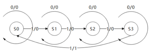
如图所示为两种状态机中的一种,请根据状态转移图写出代码,状态转移线上的0/0等表示的意思是过程中data/flag的值。
要求:
1、 必须使用对应类型的状态机
2、 使用三段式描述方法,输出判断要求要用到对现态的判断

源代码:
1
2
3
4
5
6
7
8
9
10
11
12
13
14
15
16
17
18
19
20
21
22
23
24
25
26
27
28
29
30
31
32
33
34
35
36
37
38
39
40
41
42
43
44
45
46
47
48
49
50
51
52
53
module fsm1(
input wire clk ,
input wire rst ,
input wire data ,
output reg flag
);
//状态定义
parameter S0 = 2'd0,
S1 = 2'd1,
S2 = 2'd2,
S3 = 2'd3;
//现态与次态定义
reg [1 : 0] cur_state, next_state;
//1.状态跳转
always @(posedge clk or negedge rst) begin
if(~rst) begin
cur_state <= S0;
end
else begin
cur_state <= next_state;
end
end
//2.次态判断
always @(*) begin
next_state = cur_state;
case(cur_state)
S0: next_state = data ? S1 : S0;
S1: next_state = data ? S2 : S1;
S2: next_state = data ? S3 : S2;
S3: next_state = data ? S0 : S3;
endcase
end
//3.输出判断
always @(posedge clk or negedge rst) begin
if(~rst) begin
flag <= 1'b0;
end
else begin
if(cur_state == S3 && data == 1'b1) begin
flag <= 1'b1;
end
else begin
flag <= 1'b0;
end
end
end
endmodule
根据状态转移写状态机-二段式
如图所示为两种状态机中的一种,请根据状态转移图写出代码,状态转移线上的0/0等表示的意思是过程中data/flag的值。
要求:
1、 必须使用对应类型的状态机
2、 使用二段式描述方法


源代码:
1
2
3
4
5
6
7
8
9
10
11
12
13
14
15
16
17
18
19
20
21
22
23
24
25
26
27
28
29
30
31
32
33
34
35
36
37
38
39
40
41
42
43
44
45
46
47
48
49
50
51
52
53
54
55
56
module fsm2(
input wire clk ,
input wire rst ,
input wire data ,
output reg flag
);
//状态定义
parameter S0 = 3'd0,
S1 = 3'd1,
S2 = 3'd2,
S3 = 3'd3,
S4 = 3'd4;
//现态与次态定义
reg [2 : 0] cur_state, next_state;
//1.状态跳转
always @(posedge clk or negedge rst) begin
if(~rst) begin
cur_state <= S0;
end
else begin
cur_state <= next_state;
end
end
//2.次态判断与输出判断
always @(*) begin
next_state = cur_state;
flag = 1'b0;
case(cur_state)
S0: begin
next_state = data ? S1 : S0;
flag = 1'b0;
end
S1: begin
next_state = data ? S2 : S1;
flag = 1'b0;
end
S2: begin
next_state = data ? S3 : S2;
flag = 1'b0;
end
S3: begin
next_state = data ? S4 : S3;
flag = 1'b0;
end
S4: begin
next_state = data ? S1 : S0;
flag = 1'b1;
end
endcase
end
endmodule
异步FIFO**
请根据题目中给出的双口RAM代码和接口描述,实现异步FIFO,要求FIFO位宽和深度参数化可配置。
题目帮忙写好ram之后,异步FIFO的编写就比较容易了,只需读写指针的逻辑(这里要注意读写指针的使能标志【与RAM的使能标志一致(RAM读写地址的深度用读写指针的实际深度)】)、空满标志的逻辑(这里涉及到格雷码与跨时钟域):
- 读写指针相同,FIFO为空状态(“读空”的判断:需要将写指针同步到读时钟域,再与读指针判断)
- 读写指针最高位与次高位均相反,其他位相同,FIFO为满状态(“写满”的判断:需要将读指针同步到写时钟域,再与写指针判断)
源代码:
1
2
3
4
5
6
7
8
9
10
11
12
13
14
15
16
17
18
19
20
21
22
23
24
25
26
27
28
29
30
31
32
33
34
35
36
37
38
39
40
41
42
43
44
45
46
47
48
49
50
51
52
53
54
55
56
57
58
59
60
61
62
63
64
65
66
67
68
69
70
71
72
73
74
75
76
77
78
79
80
81
82
83
84
85
86
87
88
89
90
91
92
93
94
95
96
97
98
99
100
101
102
103
104
105
106
107
108
109
110
111
112
113
114
115
116
117
118
119
120
121
122
123
124
125
126
127
128
129
130
131
132
133
134
135
136
137
138
139
140
141
142
/***************************************RAM*****************************************/
module dual_port_RAM #(parameter DEPTH = 16,
parameter WIDTH = 8)(
input wclk
,input wenc
,input [$clog2(DEPTH)-1:0] waddr //深度对2取对数,得到地址的位宽。
,input [WIDTH-1:0] wdata //数据写入
,input rclk
,input renc
,input [$clog2(DEPTH)-1:0] raddr //深度对2取对数,得到地址的位宽。
,output reg [WIDTH-1:0] rdata //数据输出
);
reg [WIDTH-1:0] RAM_MEM [0:DEPTH-1];
always @(posedge wclk) begin
if(wenc)
RAM_MEM[waddr] <= wdata;
end
always @(posedge rclk) begin
if(renc)
rdata <= RAM_MEM[raddr];
end
endmodule
/***************************************AFIFO*****************************************/
module asyn_fifo#(
parameter WIDTH = 8,
parameter DEPTH = 16
)(
input wclk ,
input rclk ,
input wrstn ,
input rrstn ,
input winc ,
input rinc ,
input [WIDTH-1:0] wdata ,
output wire wfull ,
output wire rempty ,
output wire [WIDTH-1:0] rdata
);
//读写指针定义
reg [$clog2(DEPTH) : 0] write_point;
reg [$clog2(DEPTH) : 0] read_point;
//二进制码转格雷码
reg [$clog2(DEPTH) : 0] write_point_g;
reg [$clog2(DEPTH) : 0] read_point_g;
always @(posedge rclk or negedge rrstn) begin //!!!!这里其实用组合逻辑就好,这是题目要求这么写测试才能通过
if(~rrstn) begin
read_point_g <= 'd0;
end
else begin
read_point_g <= (read_point >> 1) ^ read_point;
end
end
always @(posedge wclk or negedge wrstn) begin
if(~wrstn) begin
write_point_g <= 'd0;
end
else begin
write_point_g <= (write_point >> 1) ^ write_point;
end
end
//例化双口RAM
dual_port_RAM #(
.DEPTH (DEPTH),
.WIDTH (WIDTH)
)dual_port_RAM_U1(
.wclk (wclk ),
.wenc (winc && ~wfull ),
.waddr (write_point[$clog2(DEPTH) - 1 : 0]),
.wdata (wdata),
.rclk (rclk ),
.renc (rinc && ~rempty),
.raddr (read_point[$clog2(DEPTH) - 1 : 0]),
.rdata (rdata)
);
//读写指针的控制
//写指针
always @(posedge wclk or negedge wrstn) begin
if(~wrstn) begin
write_point <= 'd0;
end
else begin
if(winc && ~wfull) begin
write_point <= write_point + 1;
end
end
end
//读指针
always @(posedge rclk or negedge rrstn) begin
if(~rrstn) begin
read_point <= 'd0;
end
else begin
if(rinc && ~rempty) begin
read_point <= read_point + 1;
end
end
end
//空满标志的判断
//将读指针同步到写时钟域:用来判断满信号
reg [($clog2(DEPTH) + 1) * 2 - 1 : 0] read_point_g_2clk_r;
wire [$clog2(DEPTH) : 0] read_point_g_2clk;
always @(posedge wclk or negedge wrstn) begin
if(~wrstn) begin
read_point_g_2clk_r <= 'd0;
end
else begin
read_point_g_2clk_r <= {read_point_g_2clk_r[$clog2(DEPTH) : 0], read_point_g};
end
end
assign read_point_g_2clk = read_point_g_2clk_r[($clog2(DEPTH) + 1) * 2 - 1 -: $clog2(DEPTH) + 1];
//将写指针同步到读时钟域:用来判断空信号
reg [($clog2(DEPTH) + 1) * 2 - 1 : 0] write_point_g_2clk_r;
wire [$clog2(DEPTH) : 0] write_point_g_2clk;
always @(posedge rclk or negedge rrstn) begin
if(~rrstn) begin
write_point_g_2clk_r <= 'd0;
end
else begin
write_point_g_2clk_r <= {write_point_g_2clk_r[$clog2(DEPTH) : 0], write_point_g};
end
end
assign write_point_g_2clk = write_point_g_2clk_r[($clog2(DEPTH) + 1) * 2 - 1 -: $clog2(DEPTH) + 1];
//利用格雷码进行判断
assign rempty = write_point_g_2clk == read_point_g;
assign wfull = (write_point_g == {~(read_point_g_2clk[$clog2(DEPTH) : $clog2(DEPTH) - 1]), read_point_g_2clk[$clog2(DEPTH) - 2 : 0]}) ? 1 : 0;
endmodule
同步FIFO*
- 根据题目提供的双口RAM代码和接口描述,实现同步FIFO,要求FIFO位宽和深度参数化可配置。
题目帮忙写好ram之后,同步FIFO的编写就比较容易了,只需读写指针的逻辑(这里要注意读写指针的使能标志【与RAM的使能标志一致(RAM读写地址的深度用读写指针的实际深度)】)、空满标志的逻辑:
- 读写指针相同,FIFO为空状态
- 读写指针最高位相反,其他位相同,FIFO为满状态
源代码:
1
2
3
4
5
6
7
8
9
10
11
12
13
14
15
16
17
18
19
20
21
22
23
24
25
26
27
28
29
30
31
32
33
34
35
36
37
38
39
40
41
42
43
44
45
46
47
48
49
50
51
52
53
54
55
56
57
58
59
60
61
62
63
64
65
66
67
68
69
70
71
72
73
74
75
76
77
78
79
80
81
82
83
84
85
86
87
88
89
90
91
92
93
94
95
96
97
98
99
100
/**********************************RAM************************************/
module dual_port_RAM #(parameter DEPTH = 16,
parameter WIDTH = 8)(
input wclk
,input wenc
,input [$clog2(DEPTH)-1:0] waddr //深度对2取对数,得到地址的位宽。
,input [WIDTH-1:0] wdata //数据写入
,input rclk
,input renc
,input [$clog2(DEPTH)-1:0] raddr //深度对2取对数,得到地址的位宽。
,output reg [WIDTH-1:0] rdata //数据输出
);
reg [WIDTH-1:0] RAM_MEM [0:DEPTH-1];
always @(posedge wclk) begin
if(wenc)
RAM_MEM[waddr] <= wdata;
end
always @(posedge rclk) begin
if(renc)
rdata <= RAM_MEM[raddr];
end
endmodule
/**********************************SFIFO************************************/
module sfifo#(
parameter WIDTH = 8,
parameter DEPTH = 16
)(
input clk ,
input rst_n ,
input winc ,
input rinc ,
input [WIDTH-1:0] wdata ,
output reg wfull ,
output reg rempty ,
output wire [WIDTH-1:0] rdata
);
//读写指针的定义
reg [$clog2(DEPTH) : 0] write_point;
reg [$clog2(DEPTH) : 0] read_point;
//例化双口RAM
dual_port_RAM #(
.DEPTH(DEPTH),
.WIDTH(WIDTH)
)dual_port_RAM_U1(
.wclk (clk ),
.wenc (winc && ~wfull ), //!!!!端口的使能信号要注意
.waddr (write_point[$clog2(DEPTH) - 1 : 0]), //!!!用写指针实际的深度
.wdata (wdata),
.rclk (clk ),
.renc (rinc && ~rempty),
.raddr (read_point[$clog2(DEPTH) - 1 : 0]), //!!!用读指针实际的深度
.rdata (rdata)
);
//读写指针的控制
//写指针
always @(posedge clk or negedge rst_n) begin
if(~rst_n) begin
write_point <= 'd0;
end
else begin
if(winc && ~wfull) begin
write_point <= write_point + 1;
end
end
end
//读指针
always @(posedge clk or negedge rst_n) begin
if(~rst_n) begin
read_point <= 'd0;
end
else begin
if(rinc && ~rempty) begin
read_point <= read_point + 1;
end
end
end
//!!!!!空满标志的判断
always @(posedge clk or negedge rst_n) begin
if(~rst_n) begin
rempty <= 'd0;
wfull <= 'd0;
end
else begin
rempty <= (write_point == read_point) ? 1 : 0;
wfull <= {write_point == {~read_point[$clog2(DEPTH)], read_point[$clog2(DEPTH) - 1 : 0]}} ? 1 : 0;
end
end
endmodule
格雷码计数器*
实现4bit位宽的格雷码计数器
源代码:(本题的测试环境有问题,但正常格雷码计数器就是这么写的)
1
2
3
4
5
6
7
8
9
10
11
12
13
14
15
16
17
18
19
20
21
22
23
24
25
26
27
28
29
30
31
32
33
34
module gray_counter(
input clk,
input rst_n,
output reg [3:0] gray_out
);
//二进制计数器
reg [3 : 0] cnt;
always @(posedge clk or negedge rst_n) begin
if(~rst_n) begin
cnt <= 'd0;
end
else begin
cnt <= cnt + 1;
end
end
//二进制转格雷码
wire [3:0] gray_out_w;
genvar i;
generate
for(i = 0; i < 3; i = i + 1) begin
assign gray_out_w[i] = cnt[i] ^ cnt[i + 1];
end
endgenerate
assign gray_out_w[3] = cnt[3];
always @(*) begin
gray_out <= gray_out_w;
end
endmodule仿真结果:

多bit MUX同步器*
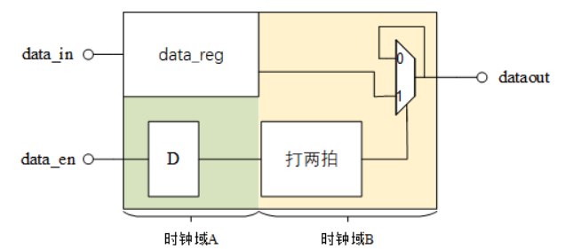
在data_en为高期间,data_in将保持不变,data_en为高至少保持3个B时钟周期。表明,当data_en为高时,可将数据进行同步。本题中data_in端数据变化频率很低,相邻两个数据间的变化,至少间隔10个B时钟周期。
题解:输入使能信号和数据都需要在本时钟域下寄存一拍
源代码:
1
2
3
4
5
6
7
8
9
10
11
12
13
14
15
16
17
18
19
20
21
22
23
24
25
26
27
28
29
30
31
32
33
34
35
36
37
38
39
40
41
42
43
44
45
46
47
48
49
50
51
52
53
54
55
module mux(
input clk_a ,
input clk_b ,
input arstn ,
input brstn ,
input [3:0] data_in ,
input data_en ,
output reg [3:0] dataout
);
//使能和输入数据在本时钟域下(clk_a)的寄存
reg [3 : 0] data_in_r_a;
reg data_en_r_a;
always @(posedge clk_a or negedge arstn) begin
if(~arstn) begin
data_en_r_a <= 'd0;
end
else begin
data_en_r_a <= data_en;
end
end
always @(posedge clk_a or negedge arstn) begin
if(~arstn) begin
data_in_r_a <= 'd0;
end
else begin
data_in_r_a <= data_in;
end
end
//跨到时钟b下使能信号打两拍
reg [1 : 0] data_en_r_b;
always @(posedge clk_b or negedge brstn) begin
if(~brstn) begin
data_en_r_b <= 'd0;
end
else begin
data_en_r_b <= {data_en_r_b[0], data_en_r_a};
end
end
//在时钟域b下的选择
always @(posedge clk_b or negedge brstn) begin
if(~brstn) begin
dataout <= 'd0;
end
else begin
dataout <= data_en_r_b[1] ? data_in_r_a : dataout;
end
end
endmodule
脉冲同步电路*
从A时钟域提取一个单时钟周期宽度脉冲,然后在新的时钟域B建立另一个单时钟宽度的脉冲。A时钟域的频率是B时钟域的10倍;A时钟域脉冲之间的间隔很大,无需考虑脉冲间隔太小的问题。
本题是用同步器解法:总体思路是将A时钟域的脉冲信号转换为电平信号,打两拍后再转换为B时钟域的脉冲信号。(适用于快到慢的脉冲同步,慢到快的脉冲同步可以直接打两拍后再边沿检测)

- 其中第一步脉冲电平转换是通过检测两个脉冲的方式,展宽输入的脉冲,以保证脉冲可以被慢时钟域检测到
源代码:
1
2
3
4
5
6
7
8
9
10
11
12
13
14
15
16
17
18
19
20
21
22
23
24
25
26
27
28
29
30
31
32
33
34
35
36
37
38
39
40
41
42
43
44
module pulse_detect(
input clk_fast ,
input clk_slow ,
input rst_n ,
input data_in ,
output dataout
);
//在快时钟域下脉冲转电平
reg data_level;
always @(posedge clk_fast or negedge rst_n) begin
if(~rst_n) begin
data_level <= 'd0;
end
else begin
data_level <= data_in ? ~data_level : data_level;
end
end
//跨时钟域,需要打两拍
reg [1 : 0] data_level_2clk;
always @(posedge clk_slow or negedge rst_n) begin
if(~rst_n) begin
data_level_2clk <= 'd0;
end
else begin
data_level_2clk <= {data_level_2clk[0], data_level};
end
end
//在慢时钟域下电平转脉冲(方法即是边沿检测)
reg data_pluse_r;
always @(posedge clk_slow or negedge rst_n) begin
if(~rst_n) begin
data_pluse_r <= 'd0;
end
else begin
data_pluse_r <= data_level_2clk[1];
end
end
assign dataout = data_pluse_r ^ data_level_2clk[1];
endmodule仿真结果:

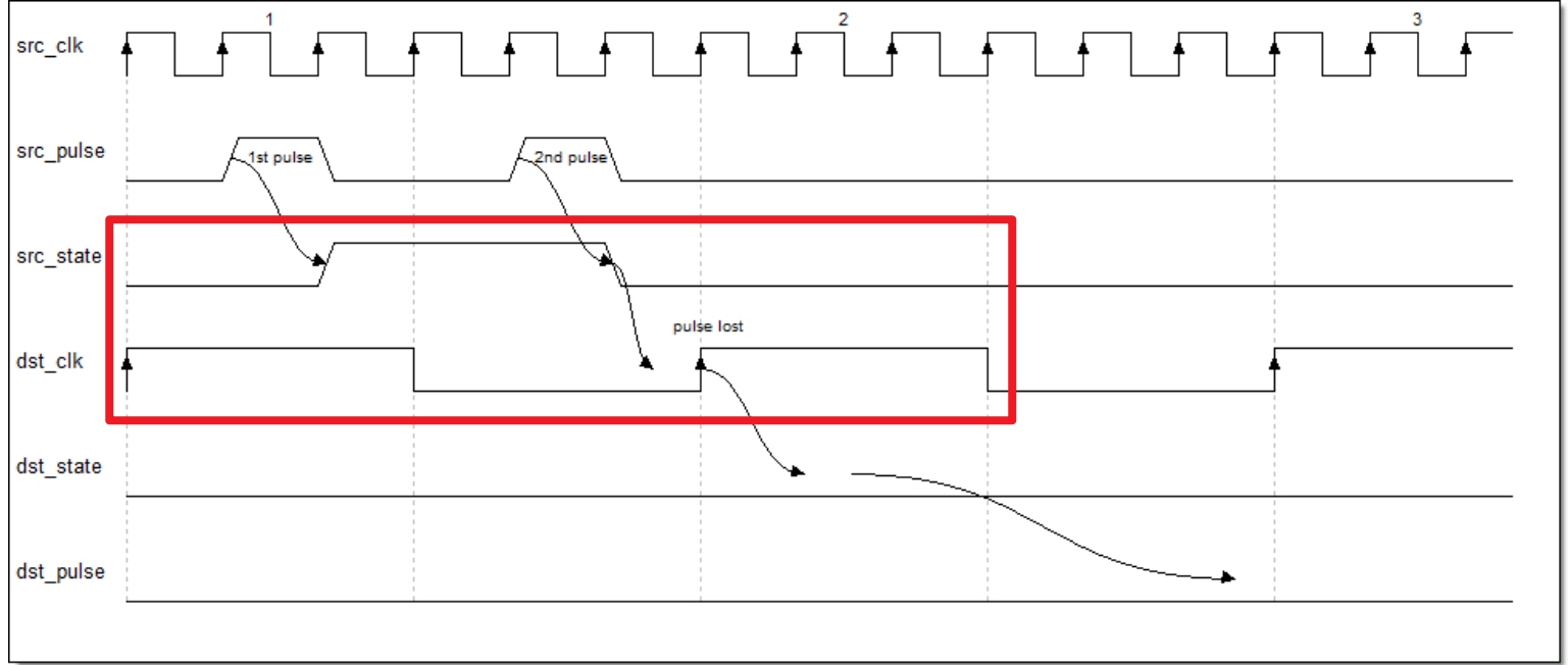
但上述方法存在当脉宽间隔过短时,慢时钟域仍捕捉不到脉冲的问题
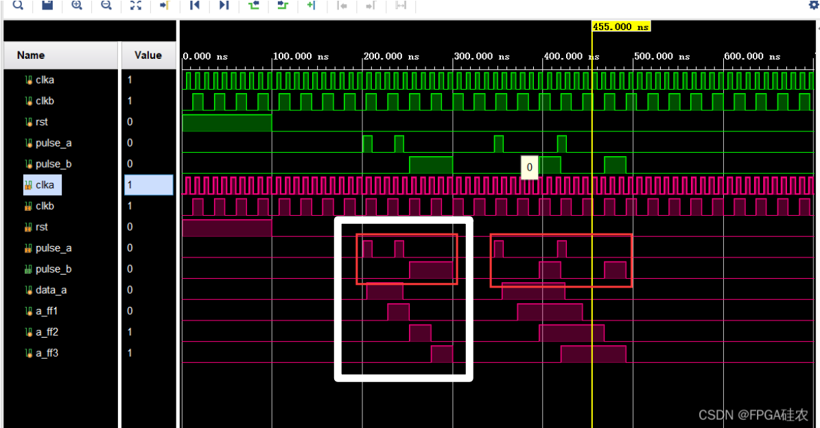
以及当两个脉冲的间隔小于两个慢时钟域周期时,会发生混叠的问题
更通用的脉冲同步方式是握手(适用于快->慢 or 慢->快 or 不清楚两侧时钟域的快慢):

目的时钟域利用上升沿检测对脉冲判断
脉冲同步到目的时钟域后,在本地缓存一拍后同步至源时钟域,作为反馈信号。该反馈信号用来使展宽后的脉宽归0
同时增加
src_sync_fail信号用来指示当前脉冲同步失败,当同步不空闲且输入脉冲时,src_sync_fail信号拉高。其主要是通过src_sync_idle来指示,该信号当且仅当脉冲展宽信号src_sync_req和反馈同步信号src_sync_ack都拉低时才有效源代码:
1
2
3
4
5
6
7
8
9
10
11
12
13
14
15
16
17
18
19
20
21
22
23
24
25
26
27
28
29
30
31
32
33
34
35
36
37
38
39
40
41
42
43
44
45
46
47
48
49
50
51
52
53
54
55
56
57
58
59
60
61
62
63
64
65
66
67
68
69
70
71
72
73
74
75
76
77
78
79
80
81
82
83
84
85
86
87
88
89
90
91
92
93
94
95
96
97
98
99
100
101
102
103
104
105
106
107
108
109
110
111
112
113
114
115
116
117
118
119
120
121
122
123
module handshake_pulse_sync
(
src_clk , //source clock
src_rst_n , //source clock reset (0: reset)
src_pulse , //source clock pulse in
src_sync_fail , //source clock sync state: 1 clock pulse if sync fail.
dst_clk , //destination clock
dst_rst_n , //destination clock reset (0:reset)
dst_pulse //destination pulse out
);
//PARA DECLARATION
//INPUT DECLARATION
input src_clk ; //source clock
input src_rst_n ; //source clock reset (0: reset)
input src_pulse ; //source clock pulse in
input dst_clk ; //destination clock
input dst_rst_n ; //destination clock reset (0:reset)
//OUTPUT DECLARATION
output src_sync_fail ; //source clock sync state: 1 clock pulse if sync fail.
output dst_pulse ; //destination pulse out
//INTER DECLARATION
wire dst_pulse ;
wire src_sync_idle ;
reg src_sync_fail ;
reg src_sync_req ;
reg src_sync_ack ;
reg ack_state_dly1 ;
reg ack_state_dly2 ;
reg req_state_dly1 ;
reg req_state_dly2 ;
reg dst_req_state ;
reg dst_sync_ack ;
//--========================MODULE SOURCE CODE==========================--
//--=========================================--
// DST Clock :
// 1. generate src_sync_fail;
// 2. generate sync req
// 3. sync dst_sync_ack
//--=========================================--
assign src_sync_idle = ~(src_sync_req | src_sync_ack );
//report an error if src_pulse when sync busy ;
always @(posedge src_clk or negedge src_rst_n)
begin
if(src_rst_n == 1'b0)
src_sync_fail <= 1'b0 ;
else if (src_pulse & (~src_sync_idle))
src_sync_fail <= 1'b1 ;
else
src_sync_fail <= 1'b0 ;
end
//set sync req if src_pulse when sync idle ;
always @(posedge src_clk or negedge src_rst_n)
begin
if(src_rst_n == 1'b0)
src_sync_req <= 1'b0 ;
else if (src_pulse & src_sync_idle)
src_sync_req <= 1'b1 ;
else if (src_sync_ack)
src_sync_req <= 1'b0 ;
end
always @(posedge src_clk or negedge src_rst_n)
begin
if(src_rst_n == 1'b0)
begin
ack_state_dly1 <= 1'b0 ;
ack_state_dly2 <= 1'b0 ;
src_sync_ack <= 1'b0 ;
end
else
begin
ack_state_dly1 <= dst_sync_ack ;
ack_state_dly2 <= ack_state_dly1 ;
src_sync_ack <= ack_state_dly2 ;
end
end
//--=========================================--
// DST Clock :
// 1. sync src sync req
// 2. generate dst pulse
// 3. generate sync ack
//--=========================================--
always @(posedge dst_clk or negedge dst_rst_n)
begin
if(dst_rst_n == 1'b0)
begin
req_state_dly1 <= 1'b0 ;
req_state_dly2 <= 1'b0 ;
dst_req_state <= 1'b0 ;
end
else
begin
req_state_dly1 <= src_sync_req ;
req_state_dly2 <= req_state_dly1 ;
dst_req_state <= req_state_dly2 ;
end
end
//Rising Edge of dst_state generate a dst_pulse;
assign dst_pulse = (~dst_req_state) & req_state_dly2 ;
//set sync ack when src_req = 1 , clear it when src_req = 0 ;
always @(posedge dst_clk or negedge dst_rst_n)
begin
if(dst_rst_n == 1'b0)
dst_sync_ack <= 1'b0;
else if (req_state_dly2)
dst_sync_ack <= 1'b1;
else
dst_sync_ack <= 1'b0;
end
endmodule仿真结果如下:

Reference:
简易秒表
请编写一个模块,实现简易秒表的功能:具有两个输出,当输出端口second从1-60循环计数,每当second计数到60,输出端口minute加一,一直到minute=60,暂停计数。
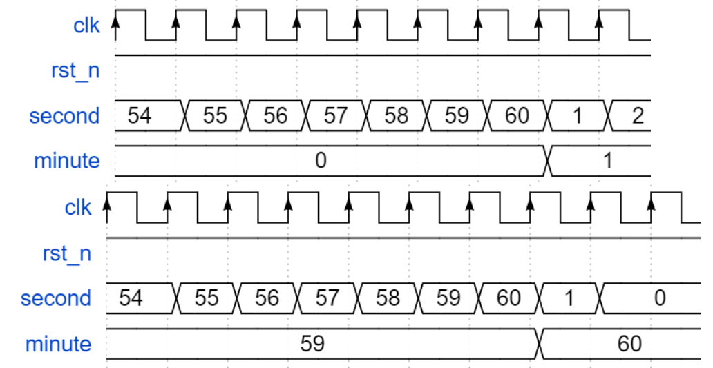
源代码:
1
2
3
4
5
6
7
8
9
10
11
12
13
14
15
16
17
18
19
20
21
22
23
24
25
26
27
28
29
30
31
32
33
34
35
36
37
38
39
40
41
42
43
44
45
46
47
48
49
module count_module(
input clk,
input rst_n,
output reg [5:0]second,
output reg [5:0]minute
);
//second计数
always @(posedge clk or negedge rst_n) begin
if(~rst_n) begin
second <= 'd0;
end
else begin
if(second == 'd60) begin
second <= 'd1;
end
else begin
if(minute == 'd60) begin
second <= 'd0;
end
else begin
second <= second + 1;
end
end
end
end
//minute计数
always @(posedge clk or negedge rst_n) begin
if(~rst_n) begin
minute <= 'd0;
end
else begin
if(minute == 'd60) begin
minute <= minute;
end
else begin
if(second == 'd60) begin
minute <= minute + 1;
end
else begin
minute <= minute;
end
end
end
end
endmodule
可置位计数器
请编写一个十六进制计数器模块,计数器输出信号递增每次到达0,给出指示信号zero,当置位信号set 有效时,将当前输出置为输入的数值set_num。
源代码:
1
2
3
4
5
6
7
8
9
10
11
12
13
14
15
16
17
18
19
20
21
22
23
24
25
26
27
28
29
30
31
32
33
34
35
36
37
38
39
40
41
42
43
44
45
46
47
48
49
50
51
module count_module2(
input clk,
input rst_n,
input set,
input [3:0] set_num,
output reg [3:0]number,
output reg zero
);
//16bit计数器
reg [3 : 0] cnt;
always @(posedge clk or negedge rst_n) begin
if(~rst_n) begin
cnt <= 'd0;
end
else begin
if(set) begin
cnt <= set_num;
end
else begin
cnt <= cnt + 1;
end
end
end
//zero输出信号
always @(posedge clk or negedge rst_n) begin
if(~rst_n) begin
zero = 'd0;
end
else begin
if(cnt == 'd0) begin
zero <= 'd1;
end
else begin
zero <= 'd0;
end
end
end
//number输出信号
always @(posedge clk or negedge rst_n) begin
if(~rst_n) begin
number <= 'd0;
end
else begin
number <= cnt;
end
end
endmodule
加减计数器
请编写一个十进制计数器模块,当mode信号为1,计数器输出信号递增,当mode信号为0,计数器输出信号递减。每次到达0,给出指示信号zero。
源代码:
1
2
3
4
5
6
7
8
9
10
11
12
13
14
15
16
17
18
19
20
21
22
23
24
25
26
27
28
29
30
31
32
33
34
35
36
37
38
39
40
41
42
43
44
45
46
47
48
49
50
51
52
module count_module3(
input clk,
input rst_n,
input mode,
output reg [3:0]number,
output reg zero
);
reg [3 : 0] cnt;
always @(posedge clk or negedge rst_n) begin
if(~rst_n) begin
cnt <= 'd0;
end
else begin
if(mode) begin
if(cnt == 9) begin
cnt <= 'd0;
end
else begin
cnt <= cnt + 1;
end
end
else begin
if(cnt == 0) begin
cnt <= 9;
end
else begin
cnt <= cnt - 1;
end
end
end
end
always @(posedge clk or negedge rst_n) begin
if(~rst_n) begin
zero <= 'd0;
end
else begin
zero <= cnt == 'd0 ? 1 : 0;
end
end
always @(posedge clk or negedge rst_n) begin
if(~rst_n) begin
number <= 'd0;
end
else begin
number <= cnt;
end
end
endmodule
单端口RAM
设计一个单端口RAM,它有: 写接口,读接口,地址接口,时钟接口和复位;存储宽度是4位,深度128。
源代码:
1
2
3
4
5
6
7
8
9
10
11
12
13
14
15
16
17
18
19
20
21
22
23
24
25
26
27
28
module RAM_1port(
input clk,
input rst,
input enb,
input [6:0]addr,
input [3:0]w_data,
output wire [3:0]r_data
);
//定义一个RAM
reg [3 : 0] ram_1 [127 : 0];
integer i;
always @(posedge clk or negedge rst) begin
if(~rst) begin
for(i = 0; i < 128; i = i + 1) begin
ram_1[i] <= 'd0;
end
end
else begin
if(enb) begin
ram_1[addr] <= w_data;
end
end
end
assign r_data = enb ? 0 : ram_1[addr];
endmodule
RAM的简单实现*
实现一个深度为8,位宽为4bit的双端口RAM,数据全部初始化为0000。具有两组端口,分别用于读数据和写数据,读写操作可以同时进行。当读数据指示信号read_en有效时,通过读地址信号read_addr读取相应位置的数据read_data,并输出;当写数据指示信号write_en有效时,通过写地址信号write_addr 和写数据write-data,向对应位置写入相应的数据。
这里需记住RAM初始化的写法模板
1
2
3
4
5
6
7
8
9
10
11
12
13
14
15
16
17
18
19
parameter INIT_FILE = "";
parameter RAM_WIDTH = 4,
RAM_DEPTH = 8;
//定义一个RAM并初始化
reg [RAM_WIDTH - 1 : 0] BRAM [RAM_DEPTH - 1:0];
//初始化通用模板
generate if (INIT_FILE != "") begin: use_init_file
initial
$readmemh(INIT_FILE, BRAM, 0, RAM_DEPTH-1);
end
else begin: init_bram_to_zero
integer ram_index;
initial
for (ram_index = 0; ram_index < RAM_DEPTH; ram_index = ram_index + 1)
BRAM[ram_index] = {RAM_WIDTH{1'b0}};
end
endgenerate源代码:
1
2
3
4
5
6
7
8
9
10
11
12
13
14
15
16
17
18
19
20
21
22
23
24
25
26
27
28
29
30
31
32
33
34
35
36
37
38
39
40
41
42
43
44
45
46
47
48
49
50
51
52
53
54
55
56
57
58module ram_mod(
input clk,
input rst_n,
input write_en,
input [7:0]write_addr,
input [3:0]write_data,
input read_en,
input [7:0]read_addr,
output reg [3:0]read_data
);
parameter   INIT_FILE = "";
parameter   RAM_WIDTH = 4,
            RAM_DEPTH = 8;

//定义一个RAM并初始化
reg [RAM_WIDTH - 1 : 0] BRAM [RAM_DEPTH - 1:0];

//初始化通用模板
generate if (INIT_FILE != "") begin: use_init_file
    initial
        $readmemh(INIT_FILE, BRAM, 0, RAM_DEPTH-1);
    end
    else begin: init_bram_to_zero
    integer ram_index;
    initial
        for (ram_index = 0; ram_index < RAM_DEPTH; ram_index = ram_index + 1)
            BRAM[ram_index] = {RAM_WIDTH{1'b0}};
    end
endgenerate
//写逻辑
always @(posedge clk or negedge rst_n) begin
if(~rst_n) begin
BRAM[write_addr] <= 'd0;
end
else begin
if(write_en) begin
BRAM[write_addr] <= write_data;
end
end
end
//读逻辑
always @(posedge clk or negedge rst_n) begin
if(~rst_n) begin
read_data <= 'd0;
end
else begin
if(read_en) begin
read_data <= BRAM[read_addr];
end
end
end
endmodule
Johnson Counter**
请用Verilog实现4位约翰逊计数器(扭环形计数器),计数器的循环状态如下。
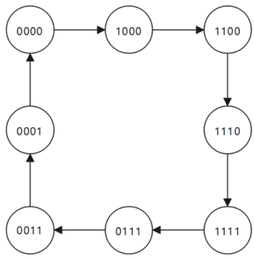
源代码:
1
2
3
4
5
6
7
8
9
10
11
12
13
14
15
16
17module JC_counter(
input clk ,
input rst_n,
output reg [3:0] Q
);
always @(posedge clk or negedge rst_n) begin
if(~rst_n) begin
Q <= 'd0;
end
else begin
Q <= {~Q[0], Q[3 : 1]};
end
end
endmodule浅浅了解了一下Johnson计数器的优点(N个移位器实现2N个状态):Johnson Counter/约翰逊计数器-CSDN博客
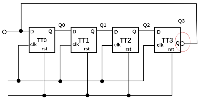
流水线乘法器*
实现4bit无符号数流水线乘法器设计。
4bit流水线乘法器的设计采用乘法竖式运算的思想,本质是将乘法运算转换为加法运算。具体实现思路如下图:

源代码:
1
2
3
4
5
6
7
8
9
10
11
12
13
14
15
16
17
18
19
20
21
22
23
24
25
26
27
28
29
30
31
32
33
34
35
36
37
38
39
40
41
42
43
44
45
46
47
48
49
50
51
52
53
54
55module multi_pipe#(
parameter size = 4
)(
input clk ,
input rst_n ,
input [size-1:0] mul_a ,
input [size-1:0] mul_b ,
output reg [size*2-1:0] mul_out
);
//中间结果暂存
wire [size * 2 - 1 : 0] temp[3 : 0];
//加法结果暂存
reg [size * 2 - 1 : 0] adder0, adder1;
//组合逻辑分解乘法->加法
genvar i;
generate
for(i = 0; i < 4; i = i + 1) begin
assign temp[i] = mul_b[i] ? mul_a << i : 'd0;
end
endgenerate
//加法树
//流水线1
always @(posedge clk or negedge rst_n) begin
if(~rst_n) begin
adder0 <= 'd0;
end
else begin
adder0 <= temp[0] + temp[1];
end
end
always @(posedge clk or negedge rst_n) begin
if(~rst_n) begin
adder1 <= 'd0;
end
else begin
adder1 <= temp[2] + temp[3];
end
end
//流水线2
always @(posedge clk or negedge rst_n) begin
if(~rst_n) begin
mul_out <= 'd0;
end
else begin
mul_out <= adder0 + adder1;
end
end
endmodule
交通灯*
要求实现一个交通红绿灯,具有红黄绿三个小指示灯和一个行人按钮,正常情况下,机动车道指示灯按照60时钟周期绿灯,5个时钟周期黄灯,10个时钟周期红灯循环。当行人按钮按下,如果剩余绿灯时间大于10个时钟,则缩短为10个时钟,小于10个时钟则保持不变。
其实题目要求的不是很清楚,是红 - 黄 - 绿循环,其实关键就在于计数器cnt的逻辑,这里有个点是当cnt=1时,将cnt赋值为下一个状态需要计数的数。
源代码:
1
2
3
4
5
6
7
8
9
10
11
12
13
14
15
16
17
18
19
20
21
22
23
24
25
26
27
28
29
30
31
32
33
34
35
36
37
38
39
40
41
42
43
44
45
46
47
48
49
50
51
52
53
54
55
56
57
58
59
60
61
62
63
64
65
66
67
68
69
70
71
72
73
74
75
76
77
78
79
80
81
82
83
84
85
86
87
88
89
90
91
92
93
94
95
96
97
98
99
100
101
102
103
104
105
106
107
108
109
110
111module triffic_light(
input rst_n, //异位复位信号,低电平有效
input clk, //时钟信号
input pass_request,
output wire[7:0]clock,
output reg red,
output reg yellow,
output reg green
);
//计数器
reg [5 : 0] cnt;
//状态定义
localparam S_IDLE = 2'd0,
S_GREEN = 2'd1,
S_YELLOW = 2'd2,
S_RED = 2'd3;
//现态与次态定义
reg [1 : 0] cur_state, next_state;
//状态跳转
always @(posedge clk or negedge rst_n) begin
if(~rst_n) begin
cur_state <= S_IDLE;
end
else begin
cur_state <= next_state;
end
end
//次态判断
always @(*) begin
next_state = cur_state;
case(cur_state)
S_IDLE: begin
if(cnt == 'd8)
next_state = S_RED;
end
S_GREEN: begin
if(cnt == 'd1)
next_state = S_RED;
end
S_YELLOW: begin
if(cnt == 'd1)
next_state = S_GREEN;
end
S_RED: begin
if(cnt == 'd1)
next_state = S_YELLOW;
end
default: begin
next_state = S_GREEN;
end
endcase
end
//计数器逻辑,控制状态跳转
always @(posedge clk or negedge rst_n) begin
if(~rst_n) begin
cnt <= 'd10;
end
else begin
case(cur_state)
S_IDLE: cnt <= cnt == 'd8 ? 'd10 : cnt - 1;
S_GREEN: cnt <= (pass_request && (cnt > 'd10)) ? 'd10 : (cnt == 'd1 ? 'd10 : cnt - 1);
S_YELLOW: cnt <= cnt == 'd1 ? 'd60 : cnt - 1;
S_RED: cnt <= cnt == 'd1 ? 'd5 : cnt - 1;
default: cnt <= 'd10;
endcase
end
end
//输出显示
//倒计时
assign clock = cnt;
//灯亮
always @(posedge clk or negedge rst_n) begin
if(~rst_n) begin
red <= 'd0;
yellow <= 'd0;
green <= 'd0;
end
else begin
case(next_state)
S_GREEN: begin
red <= 'd0;
yellow <= 'd0;
green <= 'd1;
end
S_YELLOW: begin
red <= 'd0;
yellow <= 'd1;
green <= 'd0;
end
S_RED: begin
red <= 'd1;
yellow <= 'd0;
green <= 'd0;
end
default: begin
red <= 'd0;
yellow <= 'd0;
green <= 'd0;
end
endcase
end
end
endmodule
游戏机计费程序*
要求实现一个游戏机计费模块,某游戏机具有多个模式,价格不同:普通模式每分钟1元,畅玩模式每分钟收费2元,默认情况下为普通模式,在boost按键按下之后进入畅玩模式。游戏机采用预付费模式,输入端口money的数值为预付费用,在set信号有效时,将money的数值读入。输出端口remain的数值为剩余费用,当费用小于10元时,黄色信号灯yellow亮起。当费用不足时,红色信号灯red亮起,同时关闭电脑。在游戏过程中可以通过set端口续费。每次set信号有效将此时刻money的数值加到remain之中。
本题如果用状态机做反而更加麻烦,网站中有人提供了用简单逻辑实现的方法
源代码:
1
2
3
4
5
6
7
8
9
10
11
12
13
14
15
16
17
18
19
20
21
22
23
24
25
26
27
28
29
30
31
32
33
34
35
36
37
38
39
40
41
42
43
44
45
46
47module game_count(
input rst_n, //异位复位信号,低电平有效
input clk, //时钟信号
input [9:0]money,
input set,
input boost,
output reg[9:0]remain,
output reg yellow,
output reg red
);
//yellow逻辑
always @(posedge clk or negedge rst_n) begin
if(~rst_n) begin
yellow <= 1'b0;
end
else begin
yellow <= remain < 10 && remain > 0;
end
end
//red逻辑
always @(posedge clk or negedge rst_n) begin
if(~rst_n) begin
red <= 1'b0;
end
else begin
red <= boost ? remain < 2 : remain < 1;
end
end
//remain逻辑
always @(posedge clk or negedge rst_n) begin
if(~rst_n) begin
remain <= 'd0;
end
else begin
if(boost) begin
remain <= set ? remain + money : remain < 2 ? remain : remain - 2;
end
else begin
remain <= set ? remain + money : remain < 1 ? remain : remain - 1;
end
end
end
endmodule
