本节主要介绍了cordic算法的基本原理,并解释了其为什么可以用来求解余弦值和复数信号的模值,并给出了示例的verilog代码。
CORDIC算法
1.平面坐标系旋转
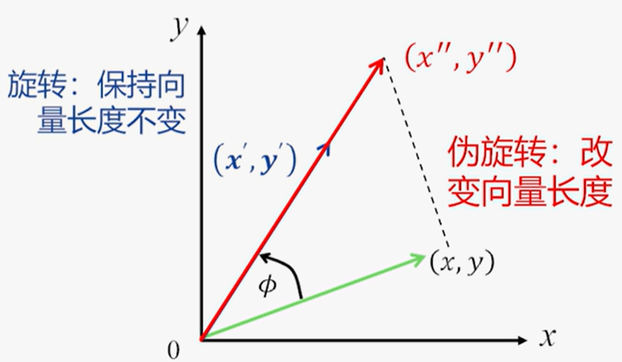
- 向量旋转公式:将向量$(x,y)$逆时针旋转$\phi$角度得到新向量$(x’,y’)$
提出公因子$cos\phi$有:
为减少计算量,引入伪旋转:
伪旋转将改变向量长度:

2.CORDIC方法
为了便于硬件的计算,采用迭代的思想,旋转角度$\phi$可以通过若干步的旋转逼近,每次旋转一个角度$\phi^i$,并约定每次旋转的角度的正切值为2的倍数,即$tan\phi^i = 2^{-i}$,这样乘以正切值就可以变成移位操作
| $i$ | $tan\phi^i=2^{-i}$ | $\phi^i$(degree) |
| :—: | :————————: | :———————: |
| 0 | $2^{-0}$ | 45° |
| 1 | $2^{-1}$ | 26.565° |
| 2 | $2^{-2}$ | 14.036° |
| 3 | $2^{-3}$ | 7.1250° |
| 4 | $2^{-4}$ | 3.5763° |
| 5 | $2^{-5}$ | 1.7899° |
| 6 | $2^{-6}$ | 0.8951° |
| 7 | $2^{-7}$ | 0.4476° |
| 8 | $2^{-8}$ | 0.2238° |
| 9 | $2^{-9}$ | 0.1119° |
| 10 | $2^{-10}$ | 0.0559° |
| 11 | $2^{-11}$ | 0.0279° |
| 12 | $2^{-12}$ | 0.0139° |
| 13 | $2^{-13}$ | 0.0069° |
| 14 | $2^{-14}$ | 0.0035° |
| 15 | $2^{-15}$ | 0.0017° |
3.旋转因子
朝着目标角度进行旋转时,可能会出现没有超过目标角度的情况,当然也存在超过目标角度的情况,而我们迭代旋转的目的是要逼近目标角度,通过多次旋转,逐渐旋转到目标角度,因此$\phi^i$有可能是逆时针旋转也有可能是顺时针旋转。故引入旋转因子$d_i$,则伪旋转坐标方程为:
写成迭代方程的形式为:
- 其中第$i$步顺时针旋转时$d_i=-1$,逆时针旋转时$d_i = 1$
4.角度累加器
用来在每次迭代过程中追踪累加的旋转角度,即本次旋转后,目标角度与此时角度的差值,其计算公式如下:
- 其中$d_i=\pm1$
- $\phi^i$代表每次旋转的角度,其需要使用LUT查找表(存储的值如上表的$\phi^i$所示)事先存储在FPGA中
- $z_0$为目标角度或0(根据不同的模式决定)
5.移位-加法算法
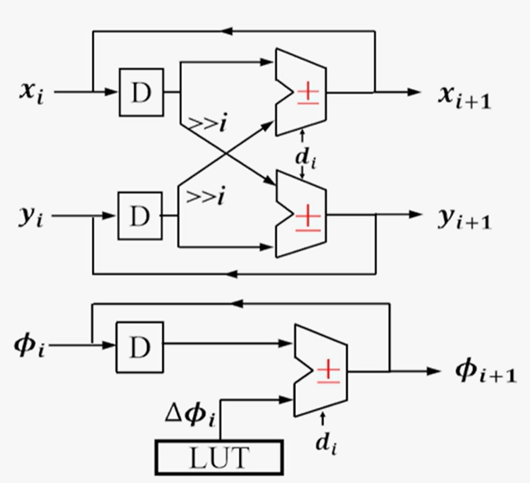
原始的算法现在已经被简化为使用伪旋转方程式来表示迭代算法
- 2次移位:$2^{-i}$用移位实现,每右移$i$位就把原来数值乘以2的$-i$次方了
- 1次查找表:每次迭代都会一个固定角度$\phi^i$的累加,用查找表实现$\phi^i$
- 3次加法:x,y,z的累加,共三次
对应迭代结构:

n级流水线结构:

6.伸缩因子
当简化算法以伪旋转时,$cos\phi$项被忽略,这样$(x_n,y_n)$就被缩放了$K_n$倍(个人认为准确来说是放大了$K_n$倍),如果迭代次数已知,可以预先计算出伸缩因子$K_n$,其计算公式如下:
- 当旋转16次之后,$K_n$基本不会变化,为1.64676,则此时$\frac1{K_n}$为0.607253
旋转模式求正余弦值
1.旋转模式的关键
旋转因子的判断:当目标角度与某次旋转后的角度差$z_i$大于0时,逆时针旋转,当$z_i$小于0时,顺时针旋转,有表达式如下:
- 注意:此时$z_0$等于目标角度
初始坐标位于$(\frac 1{K_n},0)$:其实这里可以先简单的理解为初始坐标位于$(1,0)$的位置,只是我们将问题简化为了伪旋转,最后得到的结果还需要除以$K_n$,与其这样,不如在最开始时,就将坐标设为$(\frac 1{K_n},0)$(为了后续理解方便,我们先暂且认为初始坐标位于$(1,0)$)
2.求正余弦值的原理
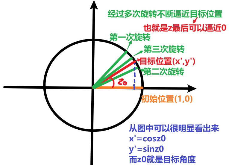
根据旋转的公式,将$(x,y)=(1,0)$带入,有:
而$(x’,y’)$是我们通过迭代计算可以求得的,则$x’$对应$cos\phi$,$y’$对应$sin\phi$
通过如下示意图可以更加形象地理解:

3.象限预处理
- 我们将上面表格的角度全部相加后约等于99.88°,则旋转角度的范围为$(-99.88°,99.88°)$,则可认为目标角度只能在第一象限和第四象限
- 若目标角度在第二和三象限,那么需要进行预处理,将目标先旋转到第一和四象限后再进行迭代运算,运算后可根据三角函数关系还原目标的真实角度
- 目标在第二象限($\phi\in(90,180)$),预处理后旋转角度$\phi-90°$,求出$\phi-90°$对应的$(x’,y’)$后,对应$\phi$的坐标为$(-y’,x’)$
- 目标在第三象限($\phi\in(180,270)$),预处理后旋转角度$\phi+90°$,求出$\phi+90°$对应的$(x’,y’)$后,对应$\phi$的坐标为$(y’,-x’)$
4.Verilog硬件实现
此处代码借鉴的Reference中第三个,主要注意以下三点
- 查找表角度的量化
- 中间结果xyz用17位存储,避免溢出
- 象限判断需要打拍,以至于在流水线结束时,当前象限对应的是流水线开始的象限。且象限判断利用输入角度phase_in[15:14]位
Cordic_to_cos.v
1
2
3
4
5
6
7
8
9
10
11
12
13
14
15
16
17
18
19
20
21
22
23
24
25
26
27
28
29
30
31
32
33
34
35
36
37
38
39
40
41
42
43
44
45
46
47
48
49
50
51
52
53
54
55
56
57
58
59
60
61
62
63
64
65
66
67
68
69
70
71
72
73
74
75
76
77
78
79
80
81
82
83
84
85
86
87
88
89
90
91
92
93
94
95
96
97
98
99
100
101
102
103
104
105
106
107
108
109
110
111
112
113
114
115
116
117
118
119
120
121
122
123
124
125
126
127
128
129
130
131
132
133
134
135
136
137
138
139
140
141
142
143
144
145
146
147
148
149
150
151
152
153
154
155
156
157
158
159
160
161
162
163
164
165
166
167
168
169
170
171
172
173
174
175
176
177
178
179
180
181
182
183
184
185
186
187
188
189
190
191
192
193
194
195
196
197
198
199
200
201
202
203
204
205
206
207
208
209
210
211
212
213
214
215
216
217
218
219
220
221
222
223
224
225
226
227
228
229
230
231
232
233
234
235
236
237
238
239
240
241
242
243
244
245
246
247
248
249
250
251
252
253
254
255
256
257
258
259
260
261
262
263
264
265
266
267
268
269
270
271
272
273
274
275
276
277
278
279
280
281
282
283
284
285
286
287
288
289
290
291
292
293
294
295
296
297
298
299
300
301
302
303
304
305
306
307
308
309
310
311
312
313
314
315
316
317
318
319
320
321
322
323
324
325
326
327
328
329
330
331
332
333
334
335
336
337
338
339
340
341
342
343
344
345
346
347
348
349
350
351
352
353
354
355
356
357
358
359
360
361
362
363
364
365
366
367
368
369
370
371
372
373
//360°--2^16,phase_in = 16bits (input [15:0] phase_in)
//1°--2^16/360
//45
//26.5651
//14.0362
//7.1250
//3.5763
//1.7899
//0.8952
//0.4476
//0.2238
//0.1119
//0.0560
//0.0280
//0.0140
//0.0070
//0.0035
//0.0018
module Cordic_to_cos
(
input clk,
//input rst_n,
//input ena,
input [15:0] phase_in,
output reg signed [16:0] eps,
output reg signed [16:0] sin,
output reg signed [16:0] cos
);
parameter PIPELINE = 16;
//parameter K = 16'h4dba;//k=0.607253*2^15
parameter K = 16'h9b74;//gian k=0.607253*2^16,9b74,n means the number pipeline
//pipeline 16-level //maybe overflow,matlab result not overflow
//MSB is signed bit,transform the sin and cos according to phase_in[15:14]
reg signed [16:0] x0=0,y0=0,z0=0;
reg signed [16:0] x1=0,y1=0,z1=0;
reg signed [16:0] x2=0,y2=0,z2=0;
reg signed [16:0] x3=0,y3=0,z3=0;
reg signed [16:0] x4=0,y4=0,z4=0;
reg signed [16:0] x5=0,y5=0,z5=0;
reg signed [16:0] x6=0,y6=0,z6=0;
reg signed [16:0] x7=0,y7=0,z7=0;
reg signed [16:0] x8=0,y8=0,z8=0;
reg signed [16:0] x9=0,y9=0,z9=0;
reg signed [16:0] x10=0,y10=0,z10=0;
reg signed [16:0] x11=0,y11=0,z11=0;
reg signed [16:0] x12=0,y12=0,z12=0;
reg signed [16:0] x13=0,y13=0,z13=0;
reg signed [16:0] x14=0,y14=0,z14=0;
reg signed [16:0] x15=0,y15=0,z15=0;
reg signed [16:0] x16=0,y16=0,z16=0;
reg [1:0] quadrant [PIPELINE:0];
integer i;
initial
begin
for(i=0;i<=PIPELINE;i=i+1)
quadrant[i] = 2'b0;
end
always @ (posedge clk)//stage 0,not pipeline
begin
x0 <= {1'b0,K}; //add one signed bit,0 means positive
y0 <= 17'b0;
z0 <= {3'b0,phase_in[13:0]};//control the phase_in to the range[0-Pi/2]
end
always @ (posedge clk)//stage 1
begin
if(z0[16])//the diff is negative so clockwise
begin
x1 <= x0 + y0;
y1 <= x0 - y0;
z1 <= z0 + `rot0;
end
else
begin
x1 <= x0 - y0;//x1 <= x0;
y1 <= x0 + y0;//y1 <= x0;
z1 <= z0 - `rot0;//reversal 45
end
end
always @ (posedge clk)//stage 2
begin
if(z1[16])//the diff is negative so clockwise
begin
x2 <= x1 + (y1>>>4'd1);
y2 <= y1 - (x1>>>4'd1);
z2 <= z1 + `rot1;//clockwise 26
end
else
begin
x2 <= x1 - (y1>>>4'd1);
y2 <= y1 + (x1>>>4'd1);
z2 <= z1 - `rot1;//anti-clockwise 26
end
end
always @ (posedge clk)//stage 3
begin
if(z2[16])//the diff is negative so clockwise
begin
x3 <= x2 + (y2>>>4'd2); //right shift n bits,divide 2^n
y3 <= y2 - (x2>>>4'd2); //left adds n bits of MSB,in first quadrant x or y are positive,MSB =0 ??
z3 <= z2 + `rot2;//clockwise 14 //difference of positive and negtive number and no round(4,5)
end
else
begin
x3 <= x2 - (y2>>>4'd2);
y3 <= y2 + (x2>>>4'd2);
z3 <= z2 - `rot2;//anti-clockwise 14
end
end
always @ (posedge clk)//stage 4
begin
if(z3[16])
begin
x4 <= x3 + (y3>>>4'd3);
y4 <= y3 - (x3>>>4'd3);
z4 <= z3 + `rot3;//clockwise 7
end
else
begin
x4 <= x3 - (y3>>>4'd3);
y4 <= y3 + (x3>>>4'd3);
z4 <= z3 - `rot3;//anti-clockwise 7
end
end
always @ (posedge clk)//stage 5
begin
if(z4[16])
begin
x5 <= x4 + (y4>>>4'd4);
y5 <= y4 - (x4>>>4'd4);
z5 <= z4 + `rot4;//clockwise 3
end
else
begin
x5 <= x4 - (y4>>>4'd4);
y5 <= y4 + (x4>>>4'd4);
z5 <= z4 - `rot4;//anti-clockwise 3
end
end
always @ (posedge clk)//STAGE 6
begin
if(z5[16])
begin
x6 <= x5 + (y5>>>4'd5);
y6 <= y5 - (x5>>>4'd5);
z6 <= z5 + `rot5;//clockwise 1
end
else
begin
x6 <= x5 - (y5>>>4'd5);
y6 <= y5 + (x5>>>4'd5);
z6 <= z5 - `rot5;//anti-clockwise 1
end
end
always @ (posedge clk)//stage 7
begin
if(z6[16])
begin
x7 <= x6 + (y6>>>4'd6);
y7 <= y6 - (x6>>>4'd6);
z7 <= z6 + `rot6;
end
else
begin
x7 <= x6 - (y6>>>4'd6);
y7 <= y6 + (x6>>>4'd6);
z7 <= z6 - `rot6;
end
end
always @ (posedge clk)//stage 8
begin
if(z7[16])
begin
x8 <= x7 + (y7>>>4'd7);
y8 <= y7 - (x7>>>4'd7);
z8 <= z7 + `rot7;
end
else
begin
x8 <= x7 - (y7>>>4'd7);
y8 <= y7 + (x7>>>4'd7);
z8 <= z7 - `rot7;
end
end
always @ (posedge clk)//stage 9
begin
if(z8[16])
begin
x9 <= x8 + (y8>>>4'd8);
y9 <= y8 - (x8>>>4'd8);
z9 <= z8 + `rot8;
end
else
begin
x9 <= x8 - (y8>>>4'd8);
y9 <= y8 + (x8>>>4'd8);
z9 <= z8 - `rot8;
end
end
always @ (posedge clk)//stage 10
begin
if(z9[16])
begin
x10 <= x9 + (y9>>>4'd9);
y10 <= y9 - (x9>>>4'd9);
z10 <= z9 + `rot9;
end
else
begin
x10 <= x9 - (y9>>>4'd9);
y10 <= y9 + (x9>>>4'd9);
z10 <= z9 - `rot9;
end
end
always @ (posedge clk)//stage 11
begin
if(z10[16])
begin
x11 <= x10 + (y10>>>4'd10);
y11 <= y10 - (x10>>>4'd10);
z11 <= z10 + `rot10;
end
else
begin
x11 <= x10 - (y10>>>4'd10);
y11 <= y10 + (x10>>>4'd10);
z11 <= z10 - `rot10;
end
end
always @ (posedge clk)//stage 12
begin
if(z11[16])
begin
x12 <= x11 + (y11>>>4'd11);
y12 <= y11 - (x11>>>4'd11);
z12 <= z11 + `rot11;
end
else
begin
x12 <= x11 - (y11>>>4'd11);
y12 <= y11 + (x11>>>4'd11);
z12 <= z11 - `rot11;
end
end
always @ (posedge clk)//stage 13
begin
if(z12[16])
begin
x13 <= x12 + (y12>>>4'd12);
y13 <= y12 - (x12>>>4'd12);
z13 <= z12 + `rot12;
end
else
begin
x13 <= x12 - (y12>>>4'd12);
y13 <= y12 + (x12>>>4'd12);
z13 <= z12 - `rot12;
end
end
always @ (posedge clk)//stage 14
begin
if(z13[16])
begin
x14 <= x13 + (y13>>>4'd13);
y14 <= y13 - (x13>>>4'd13);
z14 <= z13 + `rot13;
end
else
begin
x14 <= x13 - (y13>>>4'd13);
y14 <= y13 + (x13>>>4'd13);
z14 <= z13 - `rot13;
end
end
always @ (posedge clk)//stage 15
begin
if(z14[16])
begin
x15 <= x14 + (y14>>>4'd14);
y15 <= y14 - (x14>>>4'd14);
z15 <= z14 + `rot14;
end
else
begin
x15 <= x14 - (y14>>>4'd14);
y15 <= y14 + (x14>>>4'd14);
z15 <= z14 - `rot14;
end
end
always @ (posedge clk)//stage 16
begin
if(z15[16])
begin
x16 <= x15 + (y15>>>4'd15);
y16 <= y15 - (x15>>>4'd15);
z16 <= z15 + `rot15;
end
else
begin
x16 <= x15 - (y15>>>4'd15);
y16 <= y15 + (x15>>>4'd15);
z16 <= z15 - `rot15;
end
end
//according to the pipeline,register phase_in[15:14]
always @ (posedge clk) begin
quadrant[0] <= phase_in[15:14];
quadrant[1] <= quadrant[0];
quadrant[2] <= quadrant[1];
quadrant[3] <= quadrant[2];
quadrant[4] <= quadrant[3];
quadrant[5] <= quadrant[4];
quadrant[6] <= quadrant[5];
quadrant[7] <= quadrant[6];
quadrant[8] <= quadrant[7];
quadrant[9] <= quadrant[8];
quadrant[10] <= quadrant[9];
quadrant[11] <= quadrant[10];
quadrant[12] <= quadrant[11];
quadrant[13] <= quadrant[12];
quadrant[14] <= quadrant[13];
quadrant[15] <= quadrant[14];
quadrant[16] <= quadrant[15];
end
//alter register, according to quadrant[16] to transform the result to the right result
always @ (posedge clk)
eps <= z16;
always @ (posedge clk) begin
case(quadrant[16]) //or 15
2'b00:begin //if the phase is in first quadrant,the sin(X)=sin(A),cos(X)=cos(A)
cos <= x16;
sin <= y16;
end
2'b01:begin //if the phase is in second quadrant,the sin(X)=sin(A+90)=cosA,cos(X)=cos(A+90)=-sinA
cos <= ~(y16) + 1'b1;//-sin
sin <= x16;//cos
end
2'b10:begin //if the phase is in third quadrant,the sin(X)=sin(A+180)=-sinA,cos(X)=cos(A+180)=-cosA
cos <= ~(x16) + 1'b1;//-cos
sin <= ~(y16) + 1'b1;//-sin
end
2'b11:begin //if the phase is in forth quadrant,the sin(X)=sin(A+270)=-cosA,cos(X)=cos(A+270)=sinA
cos <= y16;//sin
sin <= ~(x16) + 1'b1;//-cos
end
endcase
end
endmoduleCordic_to_cos_tb.v
1
2
3
4
5
6
7
8
9
10
11
12
13
14
15
16
17
18
19
20
21
22
23
24
25
26
27
28
29
30
31
32
33
34
module Cordic_to_cos_tb;
// test vector input registers
reg clk;
reg [15:0] phase = 16'h0000;
// wires
wire signed [16:0] cosine_out;
wire signed [7:0] eps_out;
wire signed [16:0] sine_out;
//
localparam coef=1000;
// assign statements (if any)
Cordic_to_cos u1 (
// port map - connection between master ports and signals/registers
.clk(clk),
.cos(cosine_out),
.eps(eps_out),
.phase_in(phase),
.sin(sine_out)
);
initial begin
clk=0;
#(10000*coef) $stop;
end
always #(5*coef) clk=~clk;
always @(negedge clk) begin
phase=phase+16'h0100;
end
endmodule结果如下:

向量模式求模值
1.向量模式的关键
旋转因子的判断:与旋转模式不同,向量模式每次迭代通过判断 $y_i$的符号决定旋转方向。最终使初始向量旋转至与 X 轴的正半轴重合,向量模式每次微旋转的旋转角度存储在变量 $z$中,有:
初始坐标位于$(x,y)$(目标位置):即从$(x,y)$开始旋转,并认为此坐标对应的角度为0度,即$z_0=0$
2.求模值的原理
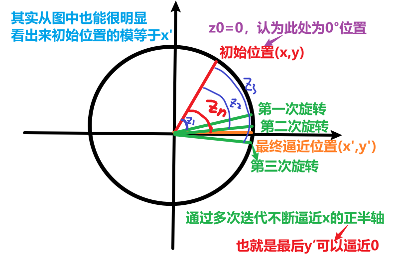
- 根据旋转的公式,将$(x’,y’)=(x’,0)$带入(因为最后会旋转到x的正半轴上,所以$y’=0$),有:
- 而$x’$是我们通过迭代计算可以求得的,则$x’$对应模值$\sqrt{x^2+y^2}$
- 由于实际旋转的时候是伪旋转,所以实际上我们取:
- $x=\frac{复数的实部}{K_n}$
- $y=\frac{复数的实部}{K_n}$
最终可以得到$x’=复数的模值$,$z=复数的角度$
通过如下示意图可以更加形象地理解:

3.象限预处理
- 向量旋转限定了初始向量必须在第一或第四象限,这就要求$x>0$。根据对称性,可以将所有的向量都搬移到第一象限,直接对$(x,y)$取绝对值即可,但是在最后输出真实结果时需要将向量再搬移回去。
4.Verilog硬件实现
参考:FPGA实现Cordic算法求解arctan和sqr(x2 + y 2)_FPGA之旅的博客-CSDN博客&spm=1018.2226.3001.4187)
Cordic_arctan.v
1
2
3
4
5
6
7
8
9
10
11
12
13
14
15
16
17
18
19
20
21
22
23
24
25
26
27
28
29
30
31
32
33
34
35
36
37
38
39
40
41
42
43
44
45
46
47
48
49
50
51
52
53
54
55
56
57
58
59
60
61
62
63
64
65
66
67
68
69
70
71
72
73
74
75
76
77
78
79
80
81
82
83
84
85
86
87
88
89
90
91
92
93
94
95
96
97
98
99
100
101
102
103
104
105
106
107
108
109
110
111
112
113
114
115
116
117
118
119
120
121
122
123
124
125
126
127
128
129
130
131
132
133
134
135
136
137
138
139
140
141
142
143
144
145
146
147
148
149
150
151
152
153
154
155
156
157
158
159
160
161
module Cordic_arctan(
input clk,
input rst_n,
input cordic_req,
output cordic_ack,
input signed[15:0] X,
input signed[15:0] Y,
output[15:0] amplitude, //幅度,偏大1.64倍,这里做了近似处理
output signed[31:0] theta //扩大了2^16
);
//45度*2^16
//26.5651度*2^16
//14.0362度*2^16
//7.1250度*2^16
//3.5763度*2^16
//1.7899度*2^16
//0.8952度*2^16
//0.4476度*2^16
//0.2238度*2^16
//0.1119度*2^16
//0.0560度*2^16
//0.0280度*2^16
//0.0140度*2^16
//0.0070度*2^16
//0.0035度*2^16
//0.0018度*2^16
reg signed[31:0] Xn[16:0];
reg signed[31:0] Yn[16:0];
reg signed[31:0] Zn[16:0];
reg[31:0] rot[15:0];
reg cal_delay[16:0];
assign cordic_ack = cal_delay[16];
assign theta = Zn[16];
assign amplitude = ((Xn[16] >>> 1) + (Xn[16] >>> 3) +(Xn[16] >>> 4)) >>> 16; ////幅度,偏大1.64倍,这里做了近似处理 ,然后缩小了2^16
always@(posedge clk)
begin
rot[0] <= `rot0;
rot[1] <= `rot1;
rot[2] <= `rot2;
rot[3] <= `rot3;
rot[4] <= `rot4;
rot[5] <= `rot5;
rot[6] <= `rot6;
rot[7] <= `rot7;
rot[8] <= `rot8;
rot[9] <= `rot9;
rot[10] <= `rot10;
rot[11] <= `rot11;
rot[12] <= `rot12;
rot[13] <= `rot13;
rot[14] <= `rot14;
rot[15] <= `rot15;
end
always@(posedge clk or negedge rst_n)
begin
if( rst_n == 1'b0)
cal_delay[0] <= 1'b0;
else
cal_delay[0] <= cordic_req;
end
genvar j;
generate
for(j = 1 ;j < 17 ; j = j + 1)
begin: loop
always@(posedge clk or negedge rst_n)
begin
if( rst_n == 1'b0)
cal_delay[j] <= 1'b0;
else
cal_delay[j] <= cal_delay[j-1];
end
end
endgenerate
//将坐标挪到第一和四项限中
always@(posedge clk or negedge rst_n)
begin
if( rst_n == 1'b0)
begin
Xn[0] <= 'd0;
Yn[0] <= 'd0;
Zn[0] <= 'd0;
end
else if( cordic_req == 1'b1)
begin
if( X < $signed(0) && Y < $signed(0))
begin
Xn[0] <= -(X << 16);
Yn[0] <= -(Y << 16);
end
else if( X < $signed(0) && Y > $signed(0))
begin
Xn[0] <= -(X << 16);
Yn[0] <= -(Y << 16);
end
else
begin
Xn[0] <= X << 16;
Yn[0] <= Y << 16;
end
Zn[0] <= 'd0;
end
else
begin
Xn[0] <= Xn[0];
Yn[0] <= Yn[0];
Zn[0] <= Zn[0];
end
end
//旋转
genvar i;
generate
for( i = 1 ;i < 17 ;i = i+1)
begin: loop2
always@(posedge clk or negedge rst_n)
begin
if( rst_n == 1'b0)
begin
Xn[i] <= 'd0;
Yn[i] <= 'd0;
Zn[i] <= 'd0;
end
else if( cal_delay[i -1] == 1'b1)
begin
if( Yn[i-1][31] == 1'b0)
begin
Xn[i] <= Xn[i-1] + (Yn[i-1] >>> (i-1));
Yn[i] <= Yn[i-1] - (Xn[i-1] >>> (i-1));
Zn[i] <= Zn[i-1] + rot[i-1];
end
else
begin
Xn[i] <= Xn[i-1] - (Yn[i-1] >>> (i-1));
Yn[i] <= Yn[i-1] + (Xn[i-1] >>> (i-1));
Zn[i] <= Zn[i-1] - rot[i-1];
end
end
else
begin
Xn[i] <= Xn[i];
Yn[i] <= Yn[i];
Zn[i] <= Zn[i];
end
end
end
endgenerate
endmodule
