本节主要介绍了数字信号处理在FPGA硬件实现中,经常需要使用的IP核(基于vivado的开发环境)。
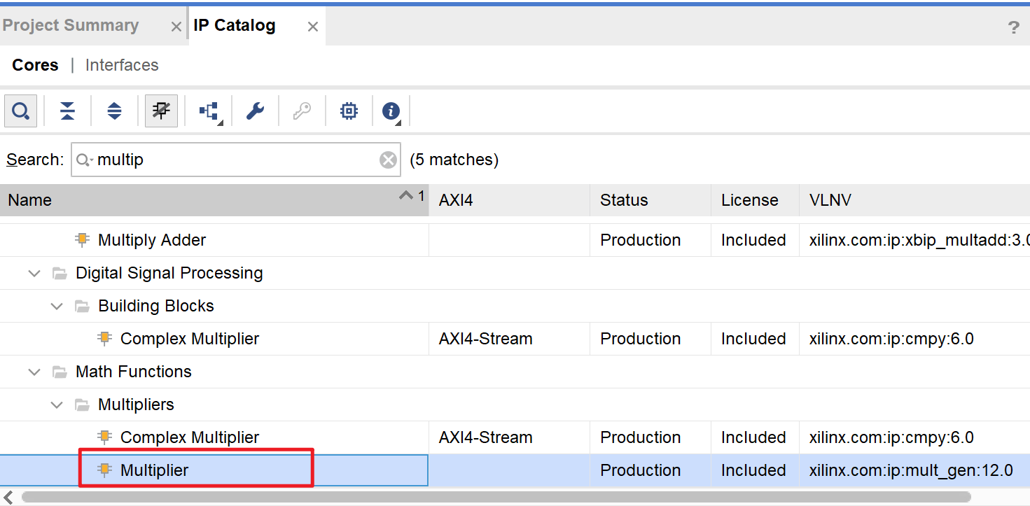
乘法器IP核的使用
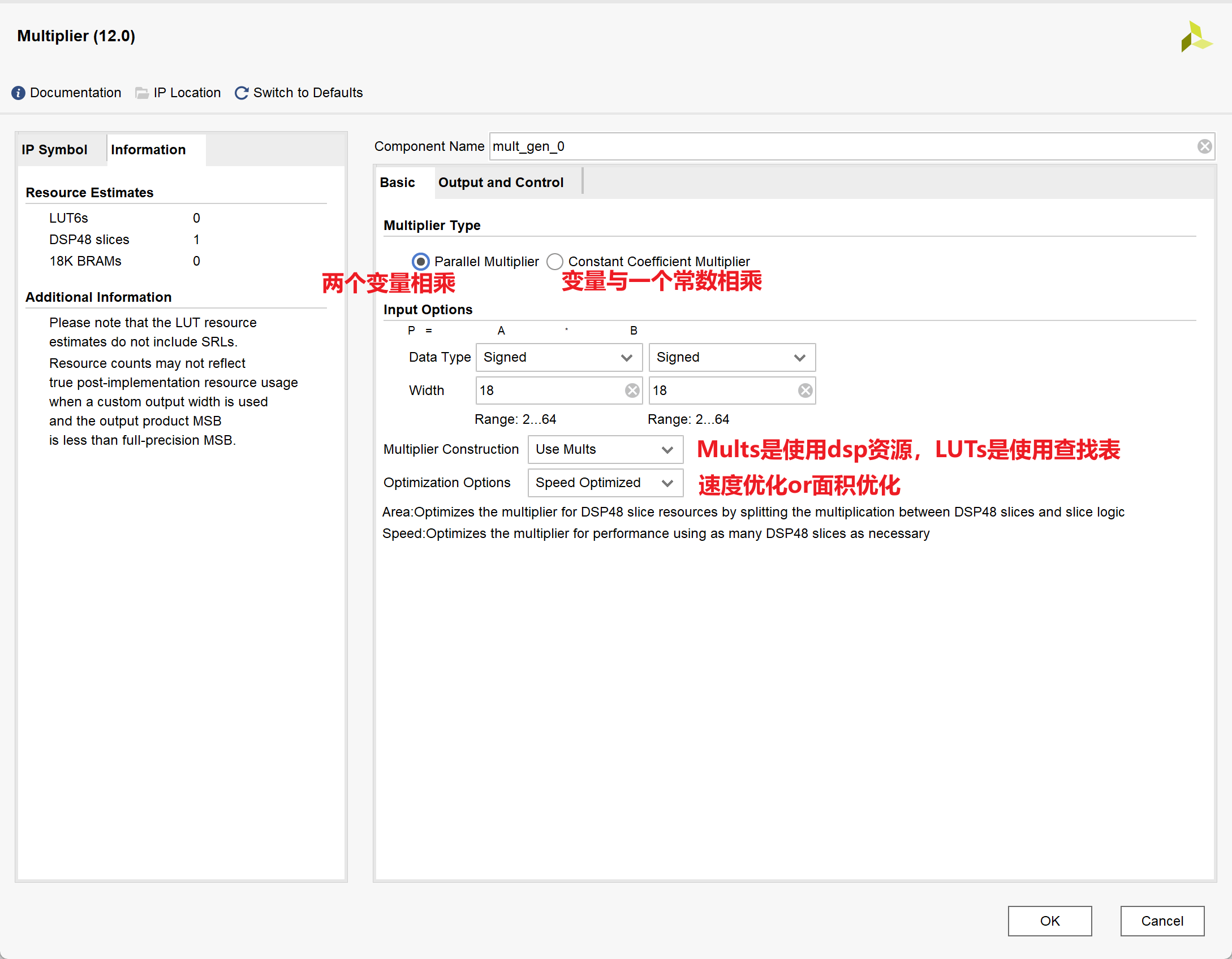
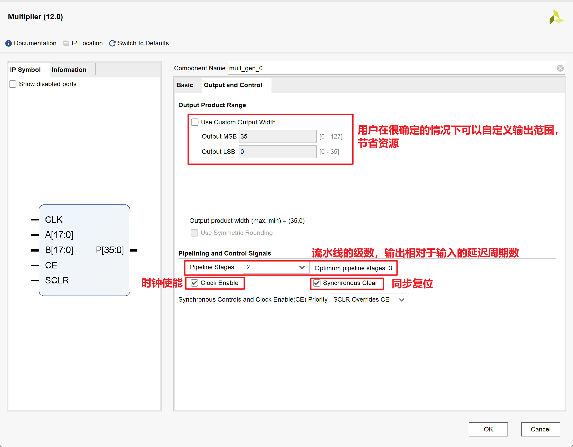
1.IP核的相关配置
2.Testbench
1 |
|
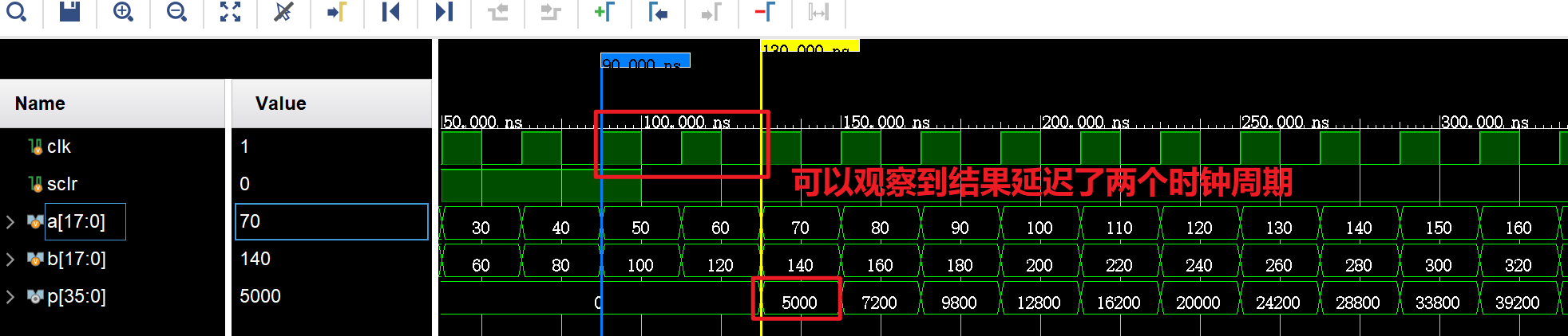
结果如下:
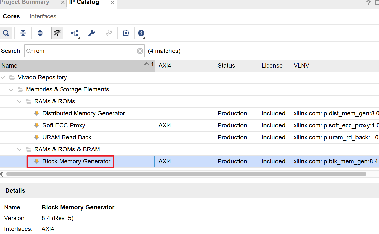
ROM IP核的使用
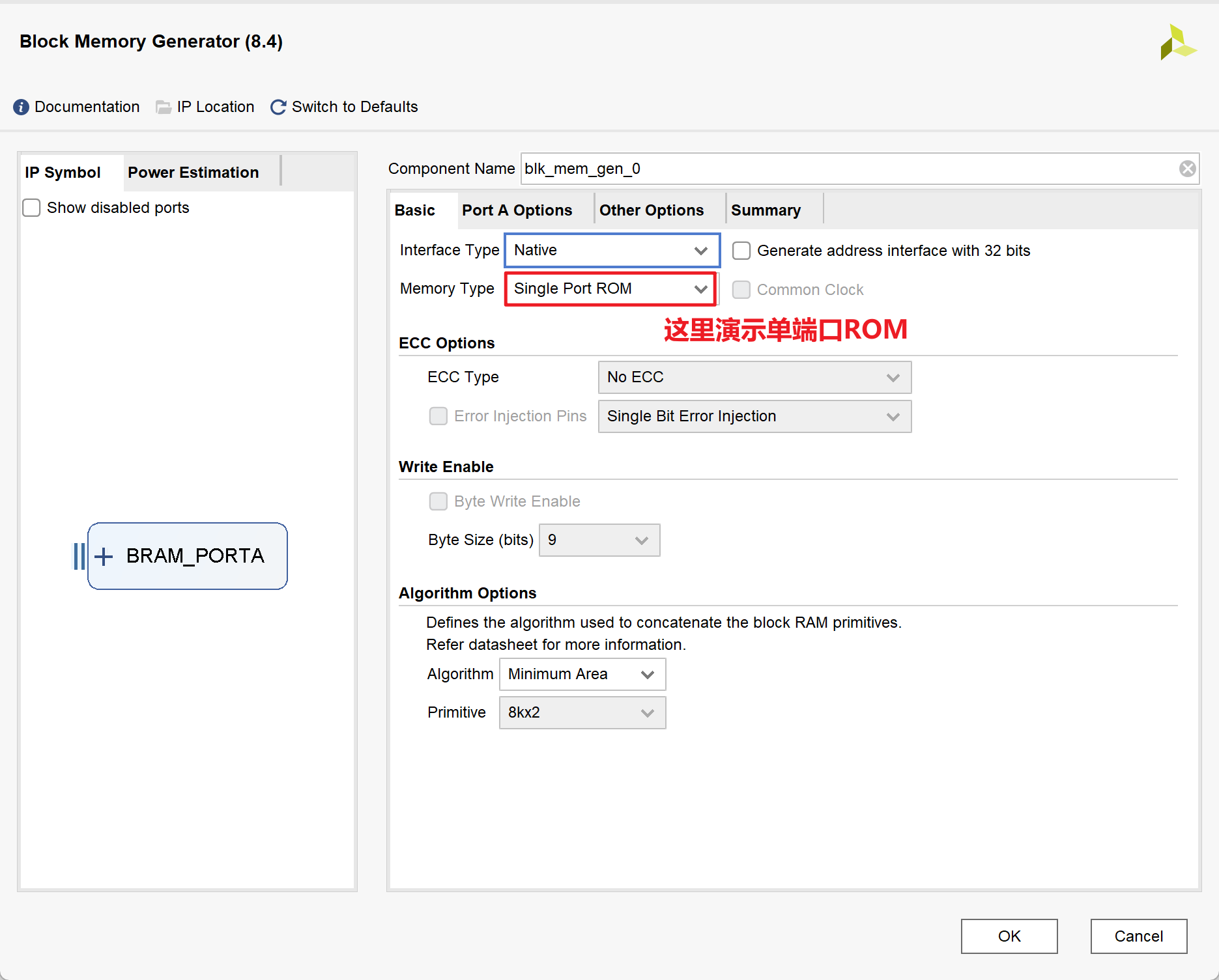
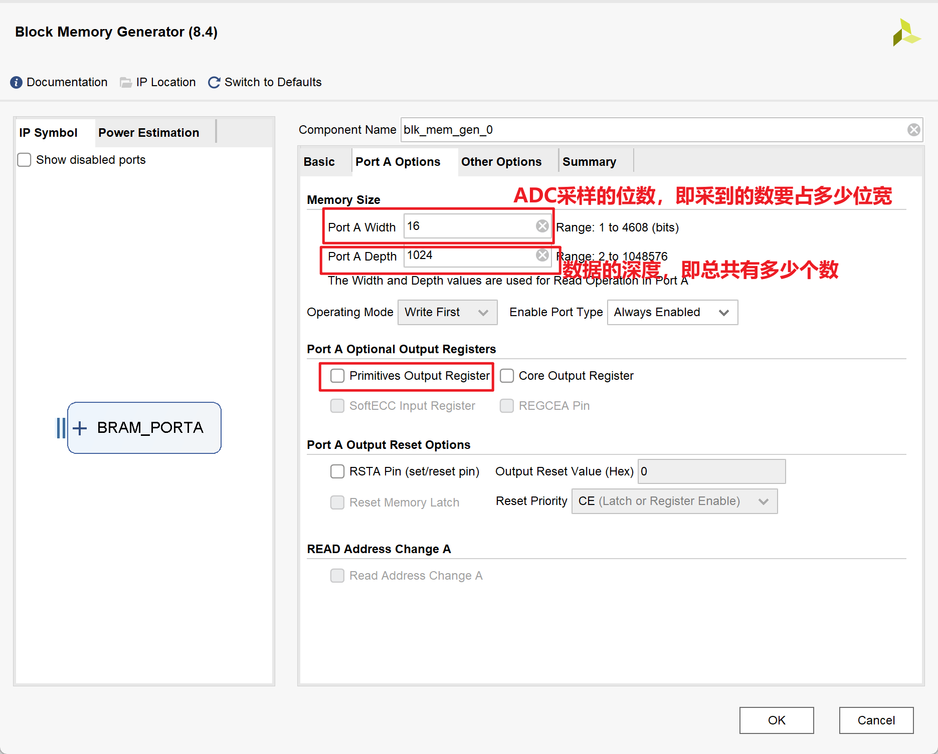
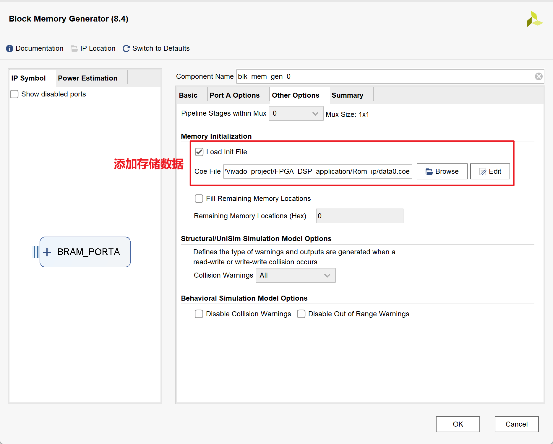
1.IP核的相关配置
2.MATLAB代码
1 | close all; |
3.Testbench
1 |
|
结果如下:
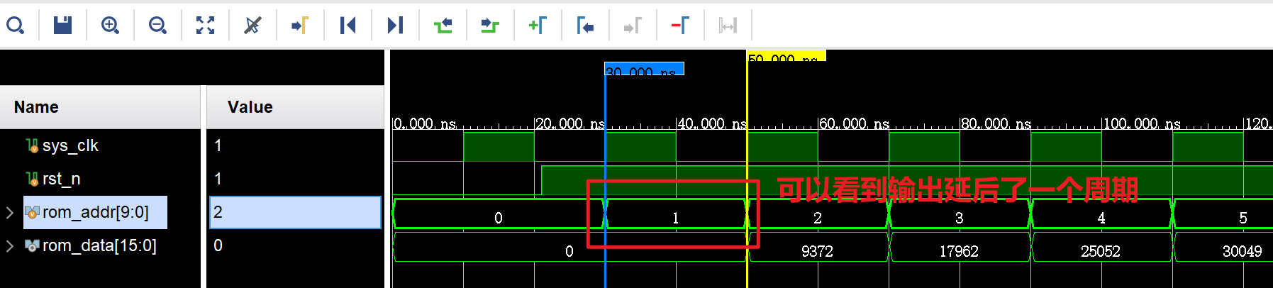
其实结构输出data数据与上升沿并不是齐平的,说明不能在上升沿结束立马得到数据,而是有一定延时
4.Reference
- Vivado ROM IP的生成和调用_ila waveform style_ML__LM的博客-CSDN博客
- Vivado中单端口和双端口RAM的区别-CSDN博客
- Vivado真双端口(TDP)RAM IP核的生成与配置详解 - 芯片天地 (ica123.com)
DDS IP核的使用
DDS的作用,产生正余弦波
其产生原理如下图,其通过在圆周上不断旋转,在y轴和x轴上的投影构成正余弦波:
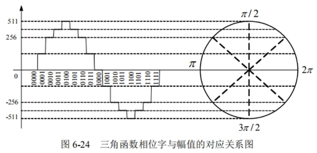
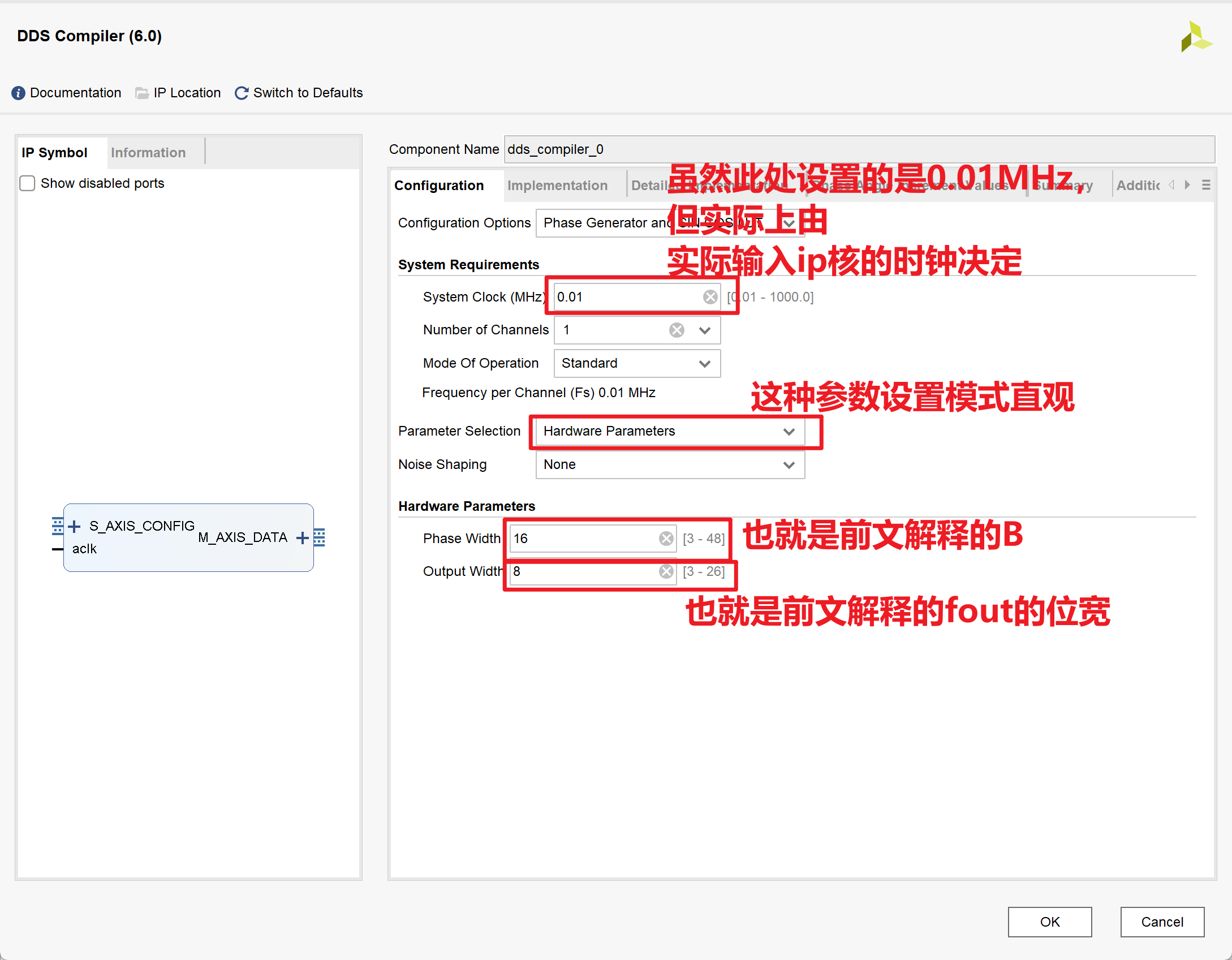
每个时钟周期旋转一格,当在一圈内旋转的格越多时(即把圆分成的份数越多时),精度越高,设格数为$2^B,B为bit数$,那么输出频率$f_{out}$为:
$$
f_{out} = \frac{f_{clk}}{2^B}
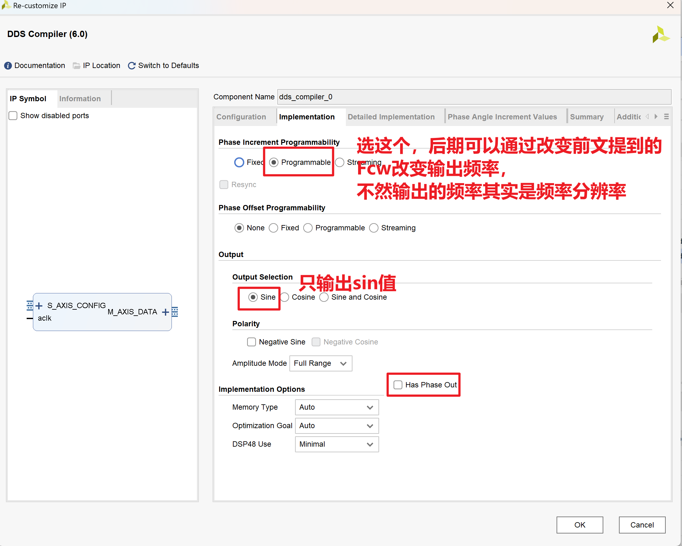
$$那么在时钟频率和bit数都确定时,如何调整输出频率呢?用通俗易懂的话来说,也就是:虽然圆被分成了很多份,但我读格子的时候,隔几格再读一个数,不就可以改变输出频率了么,设读数的间隔为$F_{cw}$,则输出频率$f_{out}$有:
$$
f_{out}=F_{cw}\cdot \frac{f_{clk}}{2^B}
$$- 其实,$\frac{f_{clk}}{2^B}$就相当于数字频率分辨率(类比FFT的采样频率$f_s$)
1.IP核的相关配置
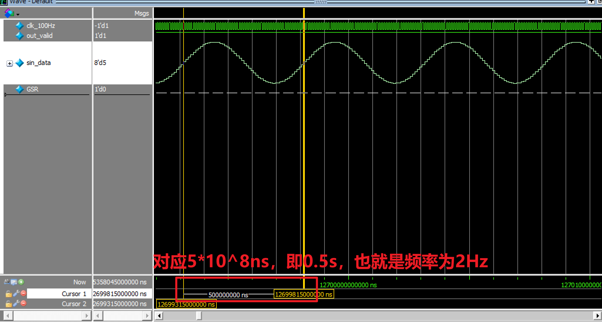
2.Testbench
1 | //这里这里仿真的尺度 |
结果如下:
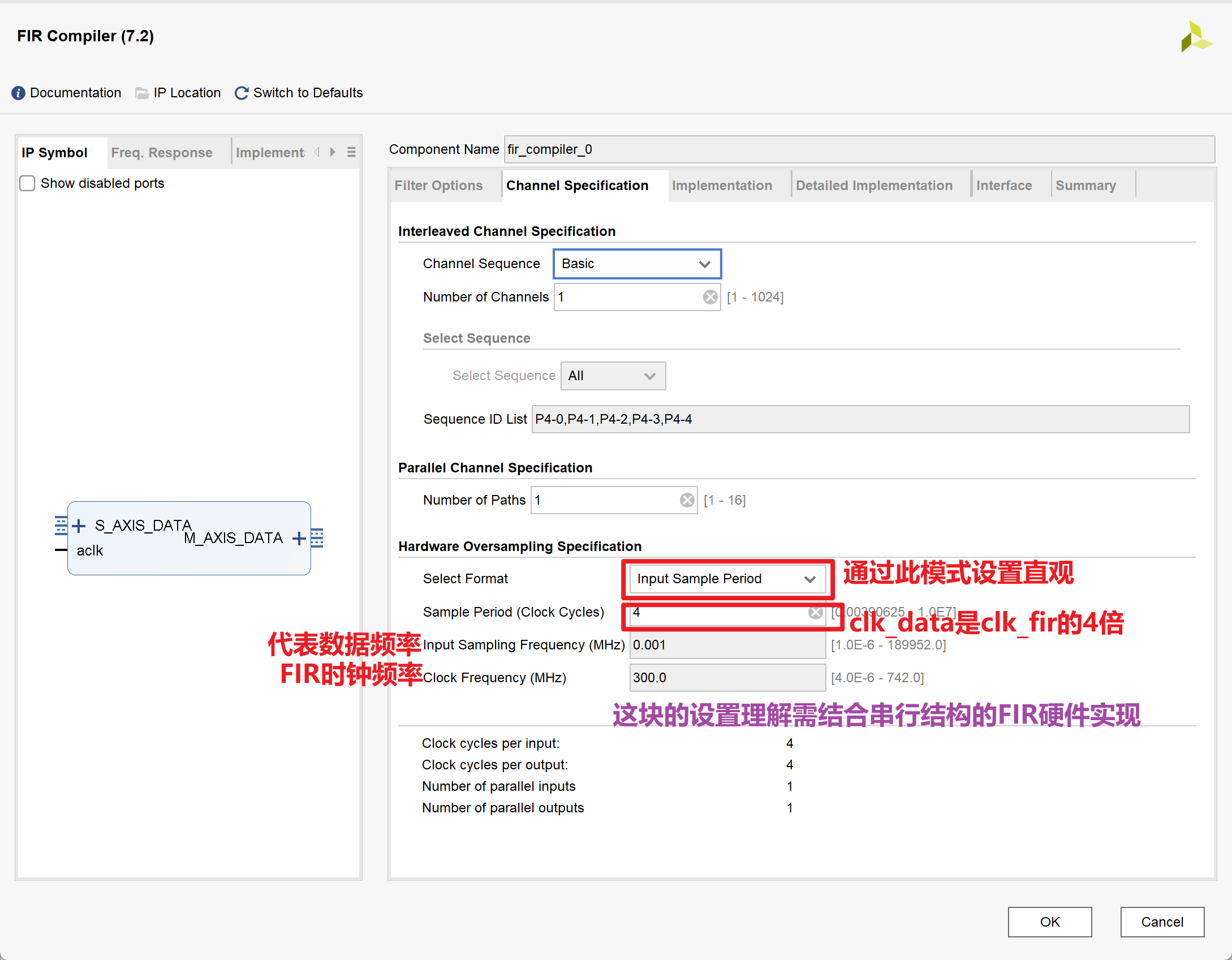
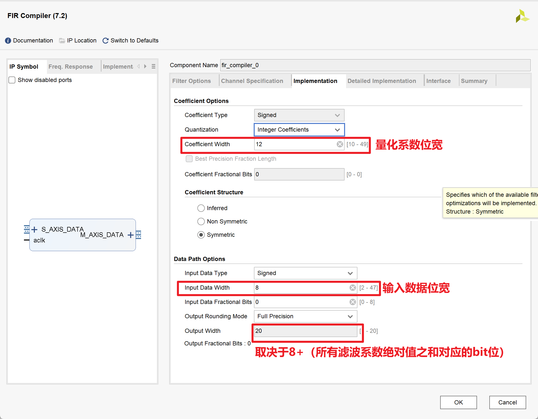
FIR IP核的使用
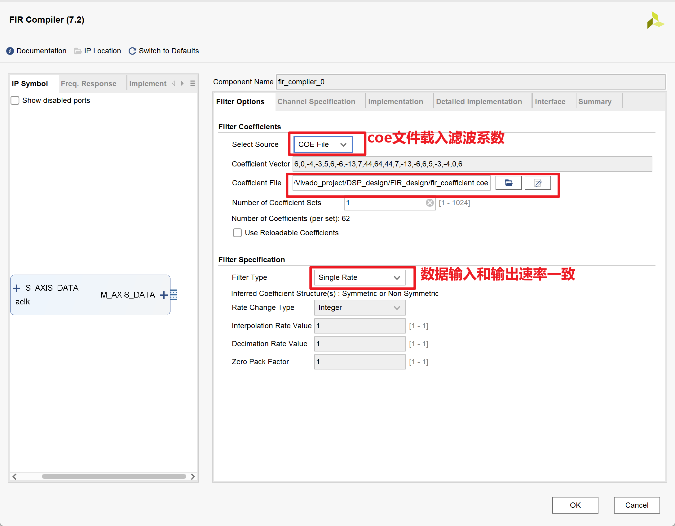
1.IP核的相关配置
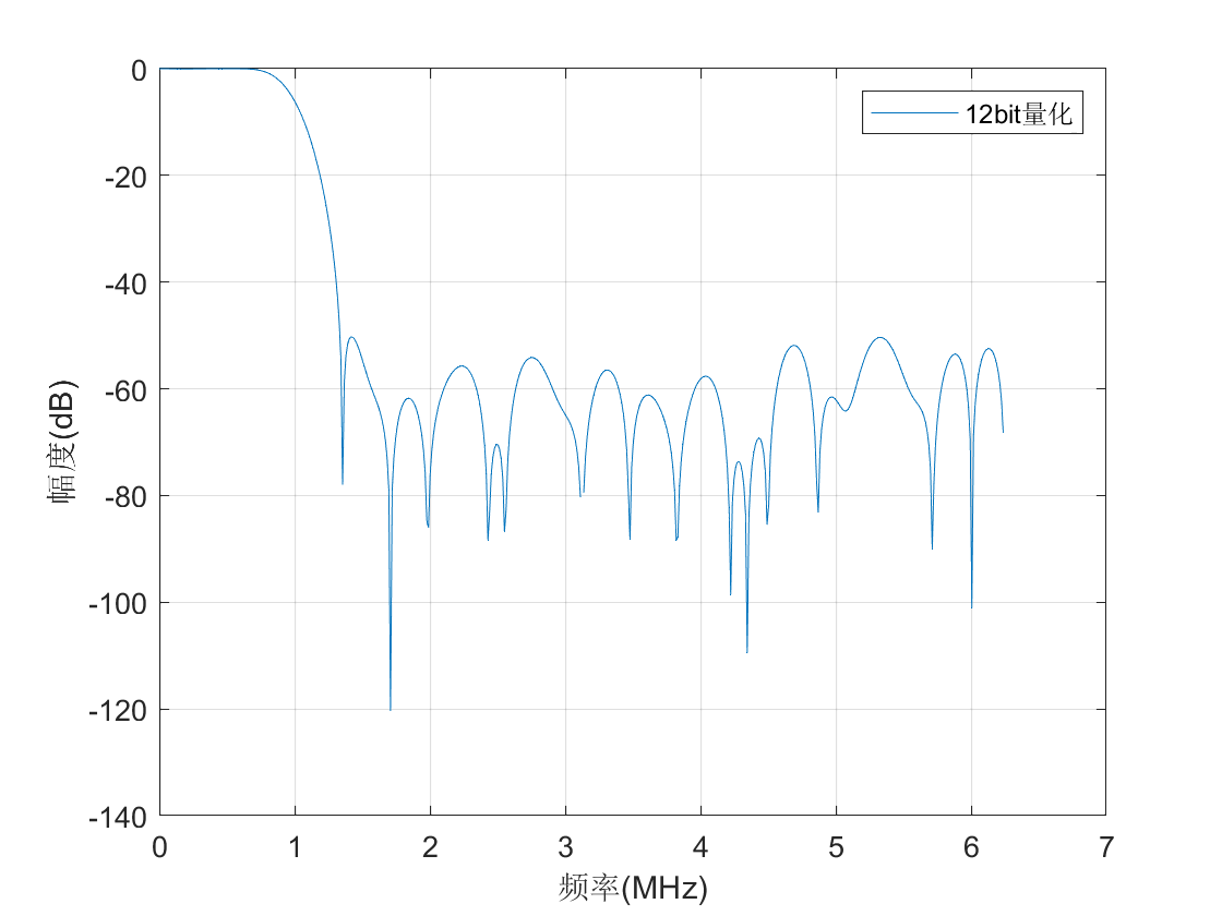
2.MATLAB代码
- 注意:下述代码中量化与在FIR滤波器设计这一节中提到的不一致,下述代码中直接乘以$2^{11}$,方便后续右移11将大小还原
- 下述matlab代码主要用来求滤波系数,其实可以用matlab中
filterDesigner可视化的GUI设计滤波器并导出coe系数文件
1 | N=62; %滤波器长度 |
3.Testbench
FIR_ip_design.v
1
2
3
4
5
6
7
8
9
10
11
12
13
14
15
16
17
18
19
20
21
22
23
24
25
26
27
28
29
30
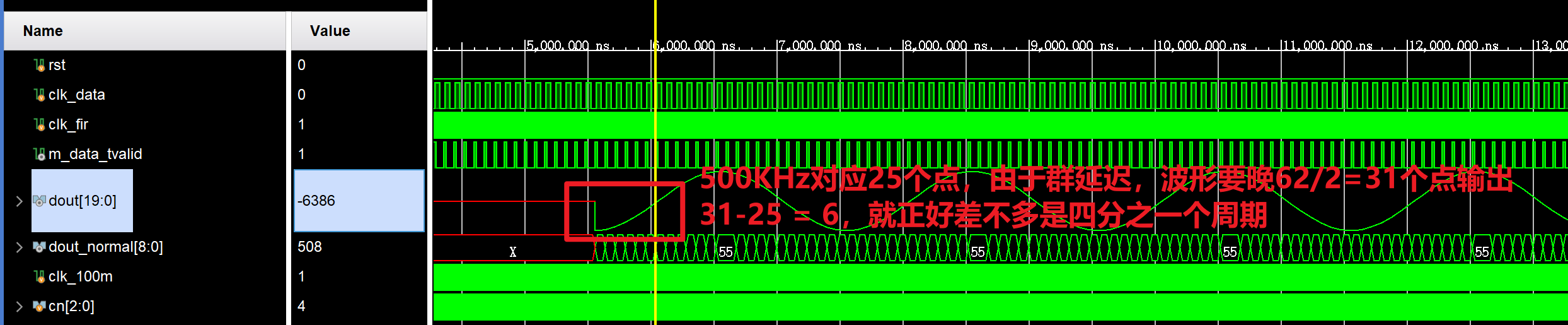
31module FIR_ip_design(
input rst,
input clk_data, //12.5MHz
input clk_fir, //50MHz
output m_data_tvalid,
output [19:0] dout,
output [8:0] dout_normal
);
wire [7:0] xin;
wire s_tready;
wire signed [23:0] m_tdata;
fir_ip_test_data u0 (
.clk(clk_data),
.dout(xin)
);
fir_compiler_0 u1 (
.aclk(clk_fir), // input clk
.s_axis_data_tvalid(1'b1),
.s_axis_data_tready(s_tready),
.s_axis_data_tdata(xin), // input [7 : 0] din
.m_axis_data_tvalid(m_data_tvalid),
.m_axis_data_tdata(m_tdata) // output [23 : 0] dout,因为axi4总线的最小单位是8bit,所以自动补齐到24bit
);
assign dout = m_tdata[19:0];
assign dout_normal = dout[19:11];
endmodulefir_ip_test_data.v
1
2
3
4
5
6
7
8
9
10
11
12
13
14
15
16
17
18
19
20
21
22
23
24
25
26
27
28
29
30
31module fir_ip_test_data(
input clk, //系统时钟为12.5MHz
output reg signed [7:0] dout //输出为500kHz和2MHz的叠加信号
);
wire signed [7:0] sin500k,sin2m; //实际DDS ip核设置的是7bit,为了使modelsim仿真不报错,设置为8bit
//生成500kHz的正弦信号
dds_for_fir_ip u1(
.aclk(clk),
.s_axis_config_tvalid(1'b1),
.s_axis_config_tdata(16'd2621),
.m_axis_data_tvalid(),
.m_axis_data_tdata(sin500k)
);
//生成2MHz的正弦信号
dds_for_fir_ip u2 (
.aclk(clk),
.s_axis_config_tvalid(1'b1),
.s_axis_config_tdata(16'd10486),
.m_axis_data_tvalid(),
.m_axis_data_tdata(sin2m)
);
//求和运算输出频率叠加信号
always @(posedge clk) begin
dout <= sin500k + sin2m;
end
endmoduleFIR_ip_tb.v
1
2
3
4
5
6
7
8
9
10
11
12
13
14
15
16
17
18
19
20
21
22
23
24
25
26
27
28
29
30
31
32
33
34
35
36
37
38
39
40
41
42
43
44
45
46module FIR_ip_tb;
// Inputs
reg rst;
reg clk_data;
reg clk_fir;
// Outputs
wire m_data_tvalid;
wire [19:0] dout;
wire [8:0] dout_normal;
// Instantiate the Unit Under Test (UUT)
FIR_ip_design uut (
.rst(rst),
.clk_data(clk_data),
.clk_fir(clk_fir),
.m_data_tvalid(m_data_tvalid),
.dout(dout),
.dout_normal(dout_normal)
);
reg clk_100m;
initial begin
// Initialize Inputs
rst = 1;
clk_data = 0;
clk_fir = 0;
clk_100m = 0;
// Wait 100 ns for global reset to finish
#100;
rst = 0;
// Add stimulus here
end
always #5 clk_100m <= !clk_100m;
reg [2:0] cn=0;
always @(posedge clk_100m) begin
cn <= cn + 1;
clk_fir <= cn[0]; //50MHz
clk_data <= cn[2]; //12.5MHz
end
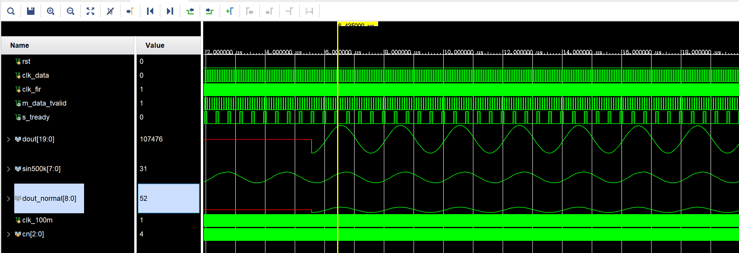
endmodule仿真结果如下:
4.Reference
- Vivado FIR滤波器IP核实现_vivado的fir滤波器ip核用法-CSDN博客
- Xilinx/ISE版 FPGA数字信号处理-完整的FIR核设计过程_哔哩哔哩_bilibili
- 基于xilinx-IP的FIR滤波器多通道实现_xilinx fir滤波-CSDN博客
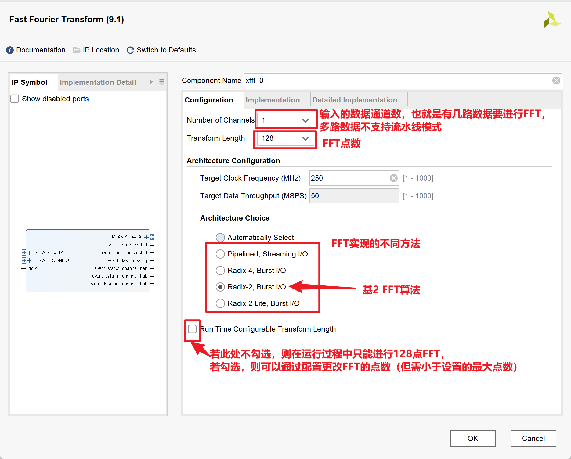
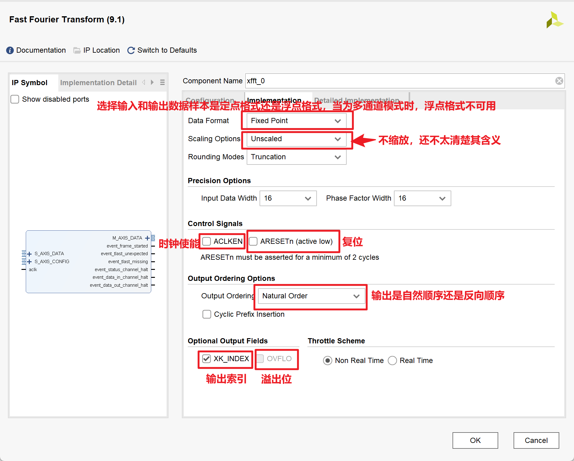
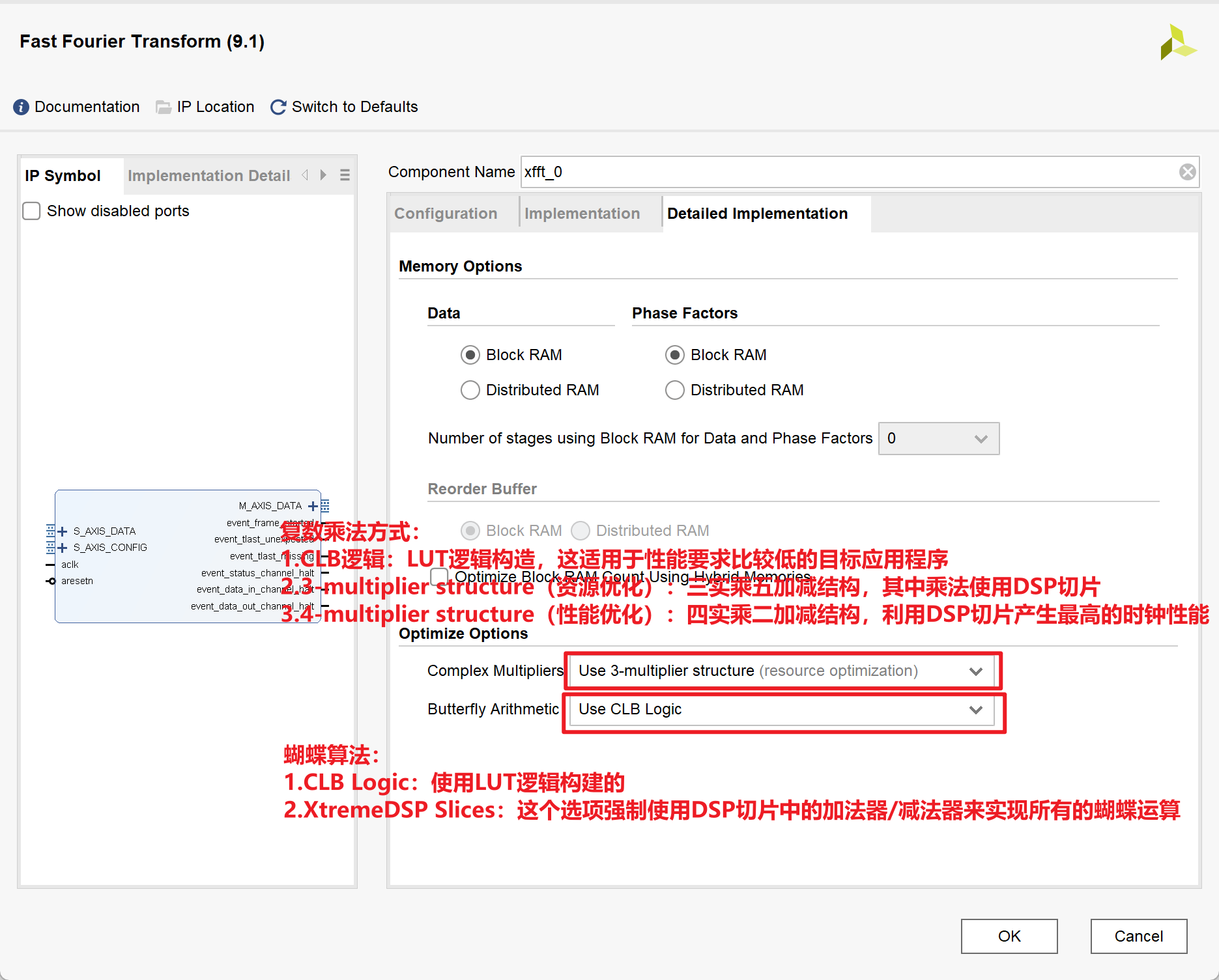
FFT IP核的使用
1.IP核的相关配置
2.MATLAB代码
1 | close all; |
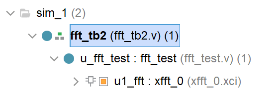
3.Testbench
1 |
|
1 |
|
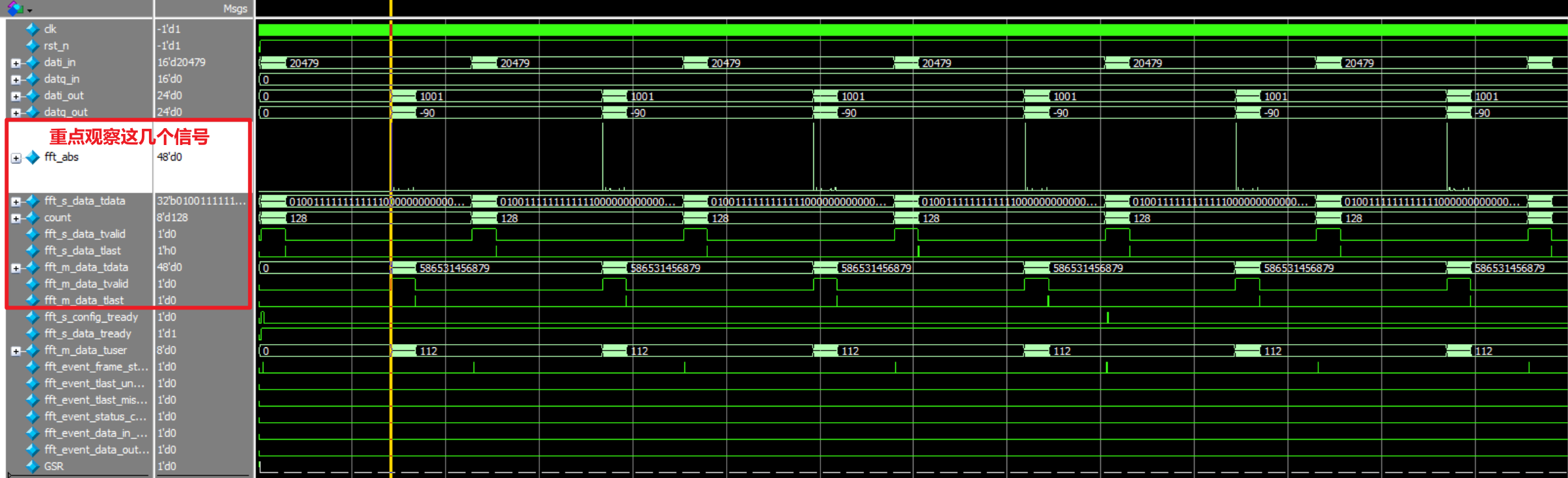
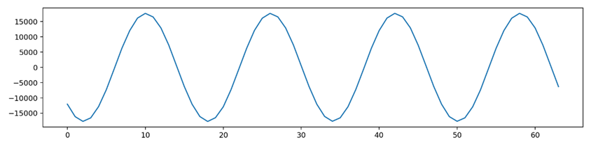
结果如下:
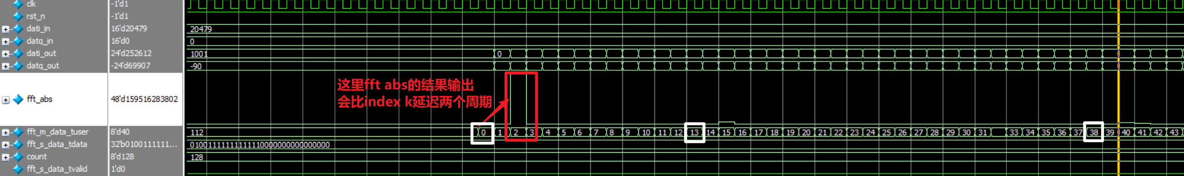
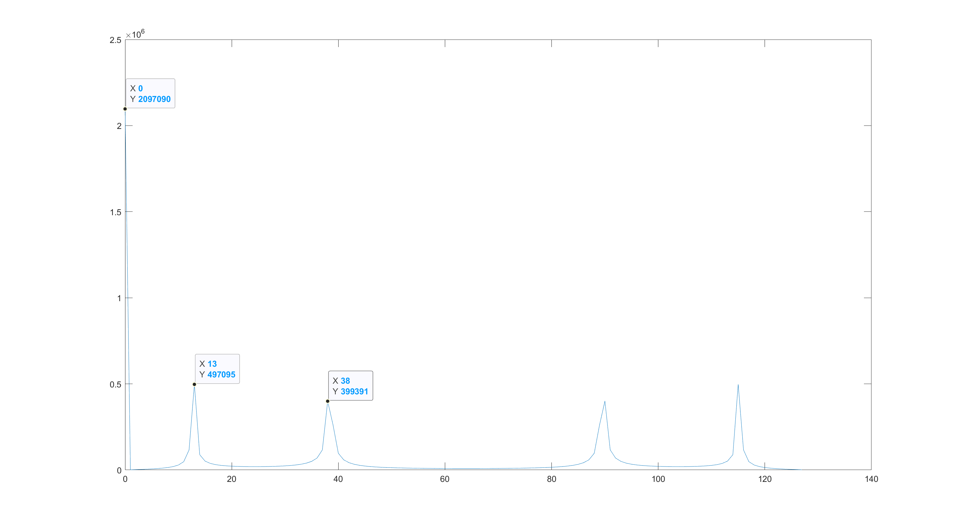
放大一点看结果的频谱图
这里的结果和matlab中的一致:
4.Reference
- Vivado Xilinx FFT IP核v9.0 使用详解(附仿真实例)_vivado fft仿真-CSDN博客
- vivado FFT ip核全解析。 - 知乎 (zhihu.com)
- Vivado中FFT IP核的使用_vivado中fft核的用法-CSDN博客
- Vivado联合ModelSim仿真设置(附图步骤)_vivado modelsim_NemoYxc的博客-CSDN博客
- VIVADO快速傅里叶变换FFT IP核详解(端口篇)_哔哩哔哩_bilibili
- VIVADO快速傅里叶变换FFT IP核详解(配置篇)_哔哩哔哩_bilibili
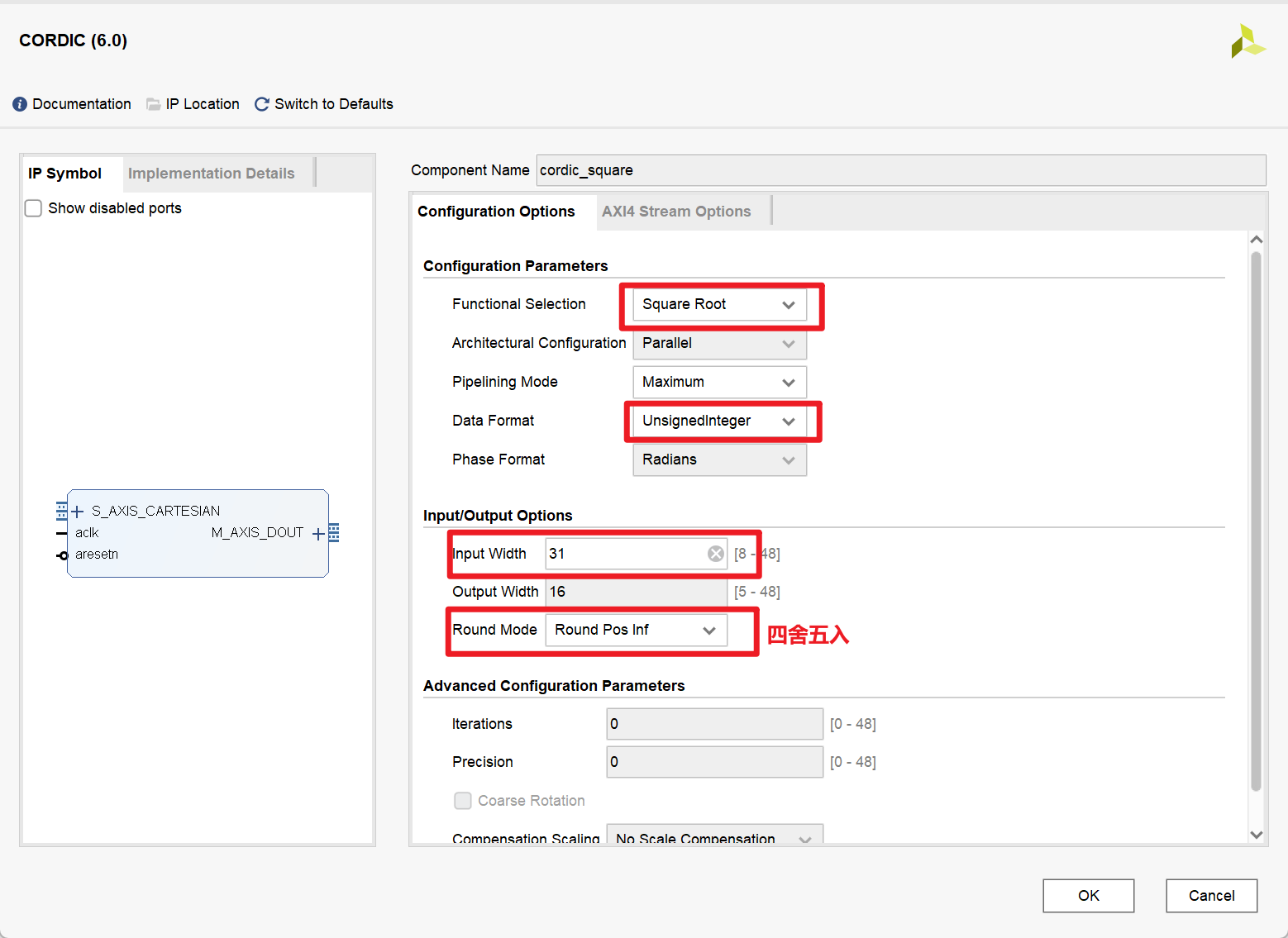
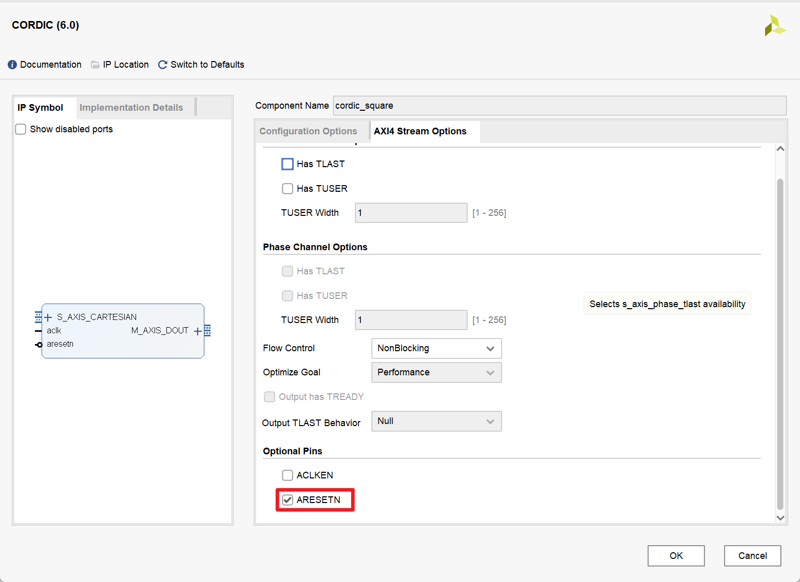
Cordic IP核的使用
1.IP核的相关配置
2.Testbench
1 |
|
RF Data Converter IP核的使用
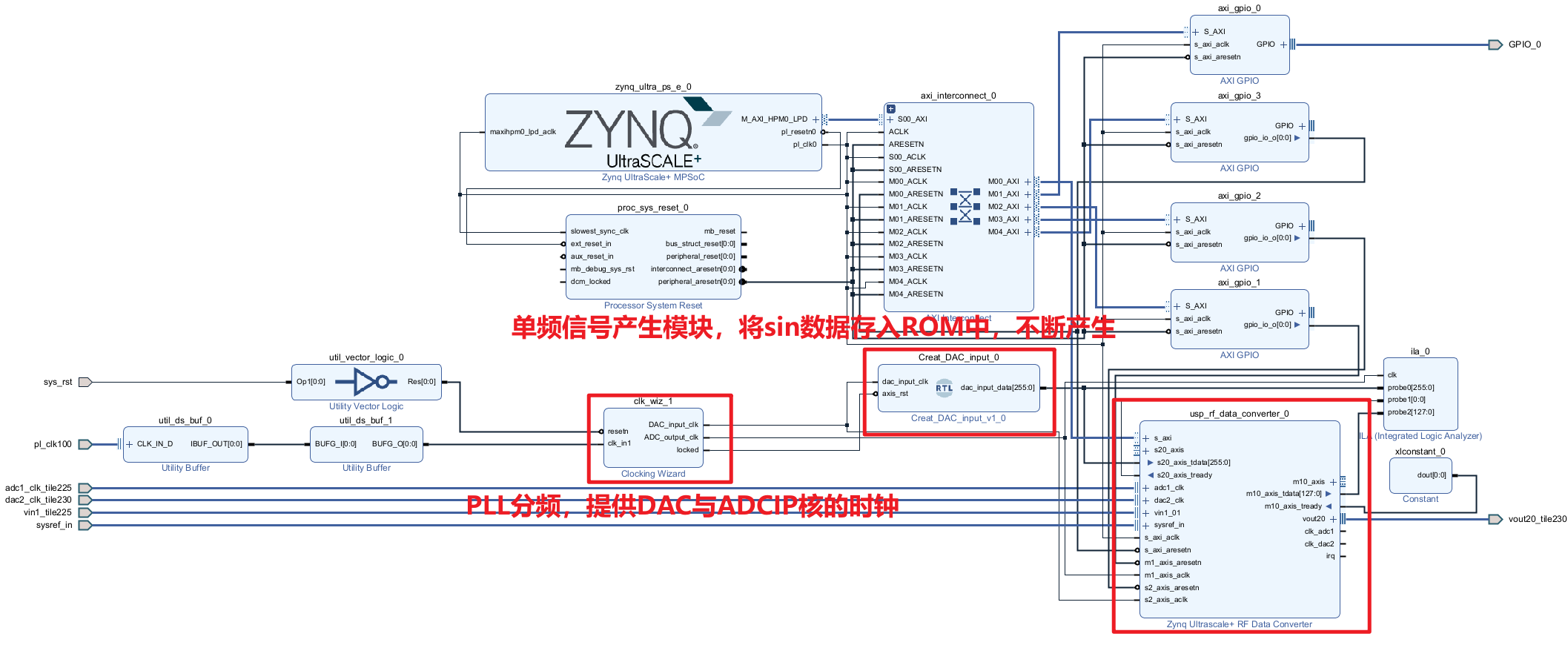
1.IP核的相关配置
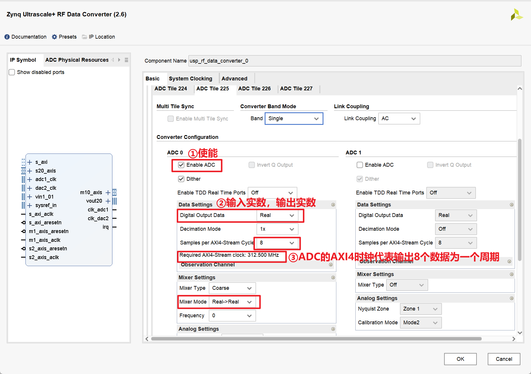
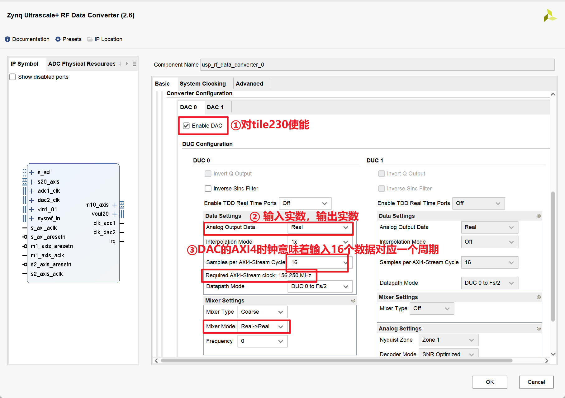
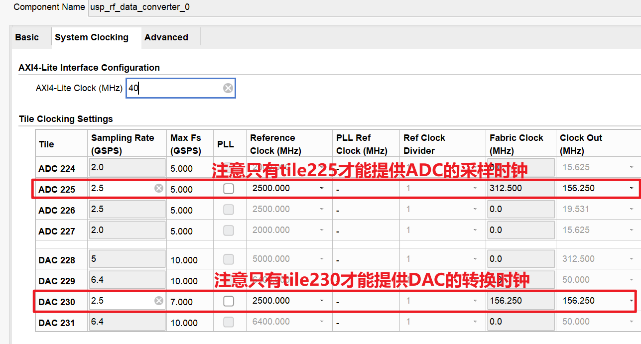
最终配置如下:
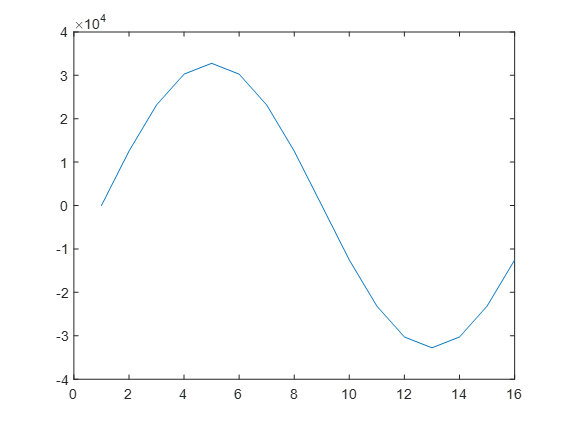
2.MATLAB代码
用来生成测试单频信号的数据
1
2
3
4
5
6
7
8
9
10
11
12
13
14
15
16
17
18
19
20
21
22
23
24
25
26
27
28
29
30
31
32
33
34
35
36
37
38
39
40
41
42
43
44
45
46
47
48
49
50
51
52
53
54
55
56
57
58
59
close all;
clear all;
clc;
%%%%%%%%%%%%%%%%%%%%%%%%%%%%%%%%%%%%%%%
% 参数定义
%%%%%%%%%%%%%%%%%%%%%%%%%%%%%%%%%%%%%%%
fc=156.25e6; % 信号频率
fs=2.5e9; % 采样频率
L=16; % 采样点数
ADC_bit=16; % 采样位数
%%%%%%%%%%%%%%%%%%%%%%%%%%%%%%%%%%%%%%%
% 产生信号
%%%%%%%%%%%%%%%%%%%%%%%%%%%%%%%%%%%%%%%
t=0:1/fs:(L-1)/fs;
noise=randn(1,length(t));
noise=0;
st=sin(2*pi*fc*t)+noise;
y=st/max(abs(st)); % 归一化
yt=round(y*(2^(ADC_bit-1)-1)); % 16bit量化
figure(1);
plot(st);
figure(2);
plot(y);
figure(3);
plot(yt);
%%%%%%%%%%%%%%%%%%%%%%%%%%%%%%%%%%%%%%%
% MATLAB生成coe文件
%%%%%%%%%%%%%%%%%%%%%%%%%%%%%%%%%%%%%%%
% 在.coe文件中
% 第一行为定义数据格式, 2代表 ROM 的数据格式为二进制。
% 从第 3 行开始到第最后一行,是这个 L(数据长度为1024)* ADC_bit(16bit) 大小 ROM 的初始化数据。
% 第一行到倒数第二行的数字后面用逗号,最后一行数字结束用分号。
fid=fopen('sin156o25M.coe','w');
fprintf(fid,'Memory_Initialization_Radix = 2;\r\n'); % 二进制
fprintf(fid,'Memory_Initialization_Vector = \r\n');
for p=1:L
B_s=dec2bin(yt(p)+(yt(p)<0)*2^ADC_bit,ADC_bit);%十进制转二进制
for q=1:ADC_bit % 16位,依次判断这16位的数值
if B_s(q)=='1'
data=1;
else
data=0;
end
fprintf(fid,'%d',data);
end
% 下面if语句的目的
% 每行数字后面用逗号(,),最后一行数字结束用分号(;)
if (p<L)
fprintf(fid,',\r\n');
else
fprintf(fid,';\r\n'); % 分号(;) 结束标志位
end
end
fclose(fid);MATLAB生成的波形:
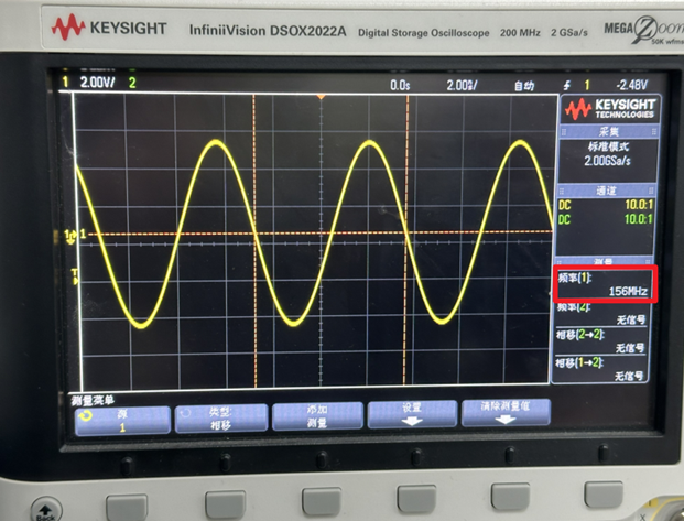
DAC结果:
3.Python代码
用来处理经过ADC后的数据,画出波形
1
2
3
4
5
6
7
8
9
10
11
12
13
14
15
16
17
18
19
20
21
22
23
24
25
26
27
28
29
30
31
32
33
34
35
36
37
38
39
40
41
42
43
44
45
46import numpy as np
from matplotlib import pyplot as plt
def split_string(input_str, chunk_size):
return [input_str[i:i + chunk_size] for i in range(0, len(input_str), chunk_size)]
if __name__ == '__main__':
hex_num = []
try:
with open('/media/data/zhl/ila_data_20240108_215000.txt', 'r') as file:
for line in file:
number = line.strip()
hex_num.append(number)
except FileNotFoundError:
print('文件不存在')
except Exception as e:
print(f'异常:{e}')
print('文件读取完毕')
# hex_num = np.array(hex_num)
int_num = []
for line in hex_num:
# 对每一行,先reshape为16*8的样子,然后再转换数据类型
temp = split_string(line, 4)
for item in temp:
int_num.append(int(item, 16))
for i in range(0, len(int_num)):
if (int_num[i] & 0x8000) == 0x8000:
# 补码,取反加一
int_num[i] = -((int_num[i]-1) ^ 0xFFFF)
width = 2000
height = 500
dpi = 180
fig = plt.figure(figsize=(width/dpi, height/dpi), dpi=dpi)
plt.plot(int_num)
plt.tight_layout()
plt.show()
print('ok')ADC结果:
4.Reference
- RFSoC应用笔记 - RF数据转换器 -02- IP配置指南_Vuko-wxh的博客-CSDN博客
- XILINX RFSoC全面解析(五)—— Zynq UItrascale+ RF Data Converter IP核详解_zynq ultrascal + rf data converter-CSDN博客
- 特别感谢湟霖同学对本次调试的鼎力支持
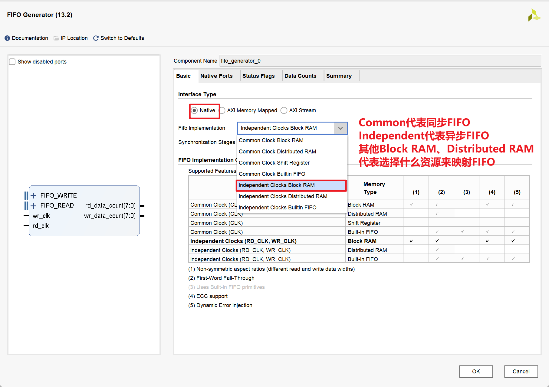
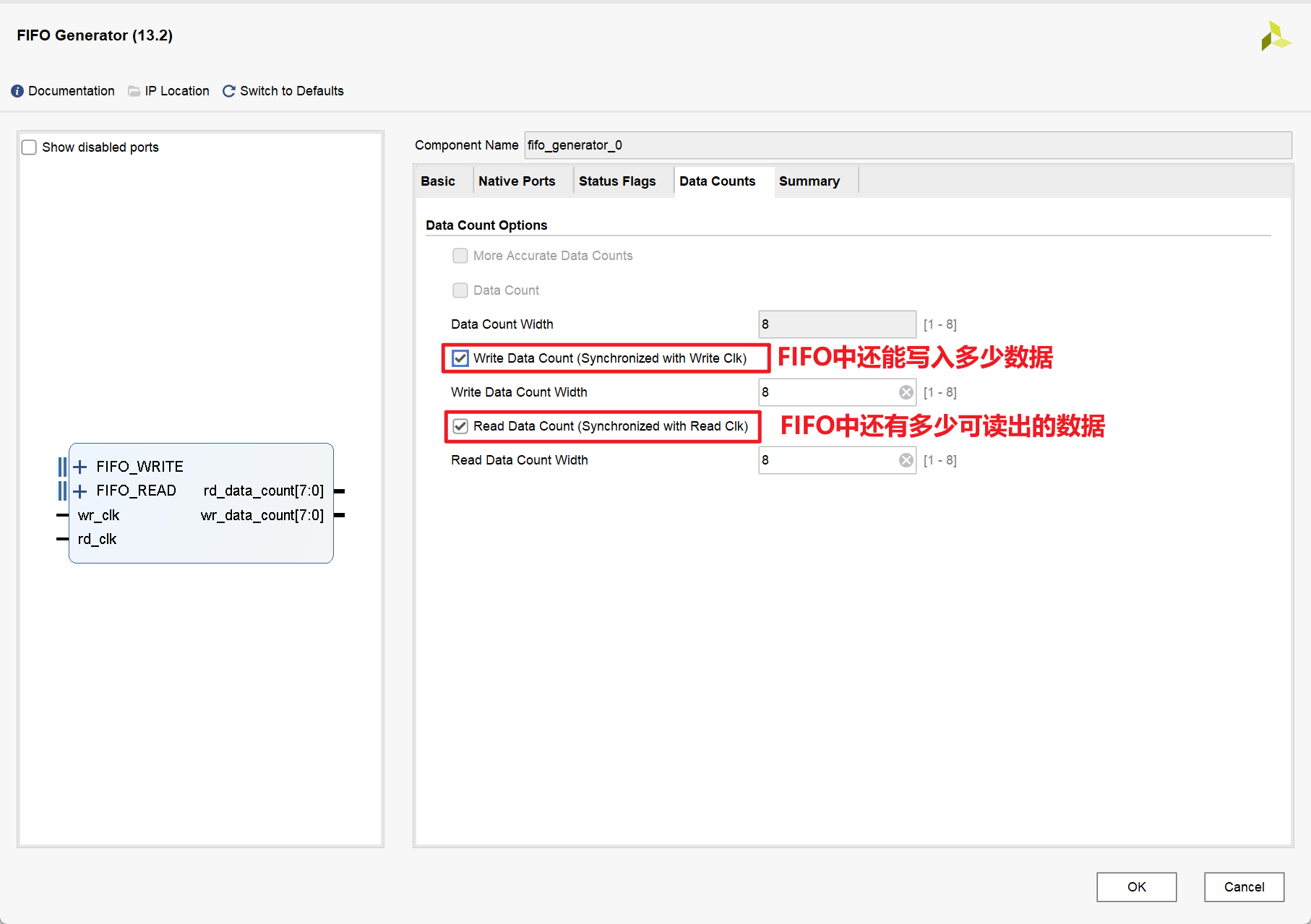
FIFO IP核的使用
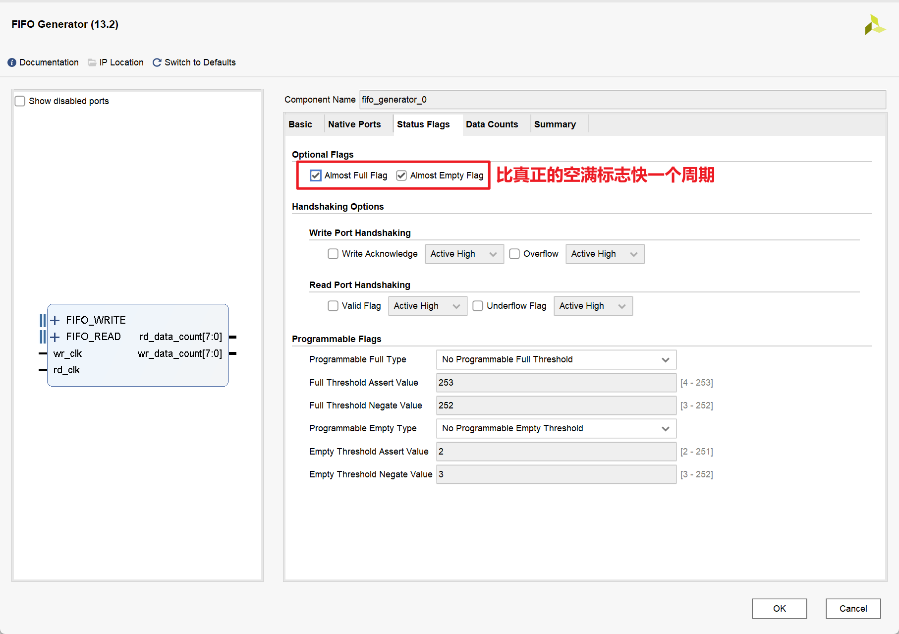
1.IP核的相关配置
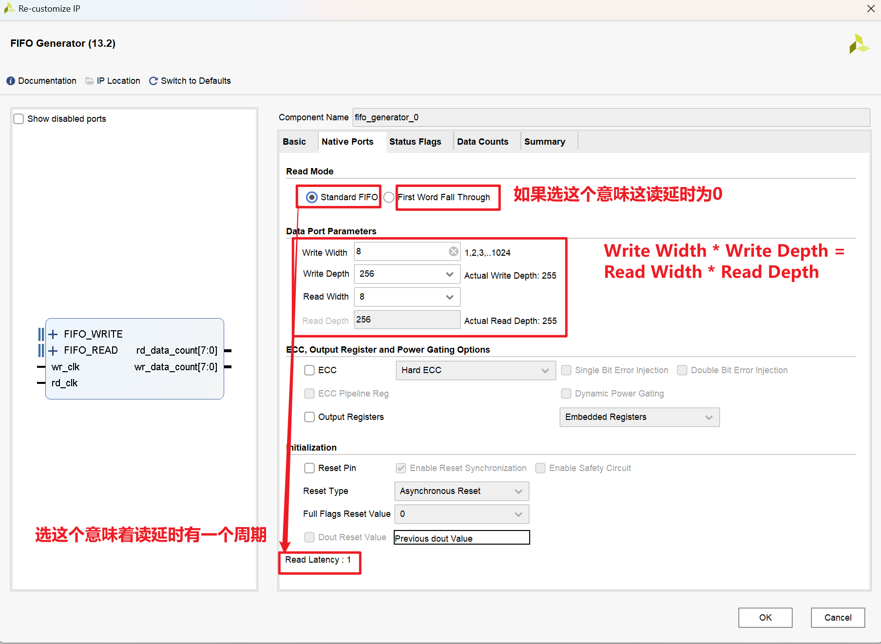
- 且对于Standard FIFO:实际位宽为255,对于First Word Fall Through:实际位宽为257
2.源代码
ip_fifo.v
1
2
3
4
5
6
7
8
9
10
11
12
13
14
15
16
17
18
19
20
21
22
23
24
25
26
27
28
29
30
31
32
33
34
35
36
37
38
39
40
41
42
43
44
45
46
47
48
49
50
51
52
53
54
55
56
57
58
59
60
61
62
63
64
65
66
module ip_fifo(
input sys_clk , // 时钟信号
input sys_rst_n // 复位信号
);
//wire define
wire fifo_wr_en ; // FIFO写使能信号
wire fifo_rd_en ; // FIFO读使能信号
wire [7:0] fifo_din ; // 写入到FIFO的数据
wire [7:0] fifo_dout ; // 从FIFO读出的数据
wire almost_full ; // FIFO将满信号
wire almost_empty ; // FIFO将空信号
wire fifo_full ; // FIFO满信号
wire fifo_empty ; // FIFO空信号
wire [7:0] fifo_wr_data_count ; // FIFO写时钟域的数据计数
wire [7:0] fifo_rd_data_count ; // FIFO读时钟域的数据计数
//*****************************************************
//** main code
//*****************************************************
//例化FIFO IP核
fifo_generator_0 fifo_ip_u1 (
.wr_clk ( sys_clk ), // input wire wr_clk
.rd_clk ( sys_clk ), // input wire rd_clk
.wr_en ( fifo_wr_en ), // input wire wr_en
.rd_en ( fifo_rd_en ), // input wire rd_en
.din ( fifo_din ), // input wire [7 : 0] din
.dout ( fifo_dout ), // output wire [7 : 0] dout
.almost_full (almost_full ), // output wire almost_full
.almost_empty (almost_empty ), // output wire almost_empty
.full ( fifo_full ), // output wire full
.empty ( fifo_empty ), // output wire empty
.wr_data_count ( fifo_wr_data_count ), // output wire [7 : 0] wr_data_count
.rd_data_count ( fifo_rd_data_count ) // output wire [7 : 0] rd_data_count
);
//例化写FIFO模块
fifo_wr u_fifo_wr(
.clk ( sys_clk ), // 写时钟
.rst_n ( sys_rst_n ), // 复位信号
.fifo_wr_en ( fifo_wr_en ) , // fifo写请求
.fifo_wr_data ( fifo_din ) , // 写入FIFO的数据
.almost_empty ( almost_empty ), // fifo空信号
.almost_full ( almost_full ) // fifo满信号
);
//例化读FIFO模块
fifo_rd u_fifo_rd(
.clk ( sys_clk ), // 读时钟
.rst_n ( sys_rst_n ), // 复位信号
.fifo_rd_en ( fifo_rd_en ), // fifo读请求
.fifo_dout ( fifo_dout ), // 从FIFO输出的数据
.almost_empty ( almost_empty ), // fifo空信号
.almost_full ( almost_full ) // fifo满信号
);
endmodulefifo_wr.v
1
2
3
4
5
6
7
8
9
10
11
12
13
14
15
16
17
18
19
20
21
22
23
24
25
26
27
28
29
30
31
32
33
34
35
36
37
38
39
40
41
42
43
44
45
46
47
48
49
50
51
52
53
54
55
56
57
58
59
60
61
62
63
64
65
66
67
68
69
70
71
72
73
74
75
76
77
78
79
80
module fifo_wr(
//mudule clock
input clk , // 时钟信号
input rst_n , // 复位信号
//FIFO interface
input almost_empty, // FIFO将空信号
input almost_full , // FIFO将满信号
output reg fifo_wr_en , // FIFO写使能
output reg [7:0] fifo_wr_data // 写入FIFO的数据
);
//reg define
reg [1:0] state ; //动作状态
reg almost_empty_d0 ; //almost_empty 延迟一拍
reg almost_empty_syn ; //almost_empty 延迟两拍
reg [3:0] dly_cnt ; //延迟计数器
//*****************************************************
//** main code
//*****************************************************
//因为 almost_empty 信号是属于FIFO读时钟域的
//所以要将其同步到写时钟域中
always@( posedge clk ) begin
if( !rst_n ) begin
almost_empty_d0 <= 1'b0 ;
almost_empty_syn <= 1'b0 ;
end
else begin
almost_empty_d0 <= almost_empty ;
almost_empty_syn <= almost_empty_d0 ;
end
end
//向FIFO中写入数据
always @(posedge clk ) begin
if(!rst_n) begin
fifo_wr_en <= 1'b0;
fifo_wr_data <= 8'd0;
state <= 2'd0;
dly_cnt <= 4'd0;
end
else begin
case(state)
2'd0: begin
if(almost_empty_syn) begin //如果检测到FIFO将被读空
state <= 2'd1; //就进入延时状态
end
else
state <= state;
end
2'd1: begin
if(dly_cnt == 4'd10) begin //延时10拍
//原因是FIFO IP核内部状态信号的更新存在延时
//延迟10拍以等待状态信号更新完毕
dly_cnt <= 4'd0;
state <= 2'd2; //开始写操作
fifo_wr_en <= 1'b1; //打开写使能
end
else
dly_cnt <= dly_cnt + 4'd1;
end
2'd2: begin
if(almost_full) begin //等待FIFO将被写满
fifo_wr_en <= 1'b0; //关闭写使能
fifo_wr_data <= 8'd0;
state <= 2'd0; //回到第一个状态
end
else begin //如果FIFO没有被写满
fifo_wr_en <= 1'b1; //则持续打开写使能
fifo_wr_data <= fifo_wr_data + 1'd1; //且写数据值持续累加
end
end
default : state <= 2'd0;
endcase
end
end
endmodulefifo_rd.v
1
2
3
4
5
6
7
8
9
10
11
12
13
14
15
16
17
18
19
20
21
22
23
24
25
26
27
28
29
30
31
32
33
34
35
36
37
38
39
40
41
42
43
44
45
46
47
48
49
50
51
52
53
54
55
56
57
58
59
60
61
62
63
64
65
66
67
68
69
70
71
72
73module fifo_rd(
//system clock
input clk , // 时钟信号
input rst_n , // 复位信号
//FIFO interface
input [7:0] fifo_dout , // 从FIFO读出的数据
input almost_full ,// FIFO将满信号
input almost_empty,// FIFO将空信号
output reg fifo_rd_en // FIFO读使能
);
//reg define
reg [1:0] state ; // 动作状态
reg almost_full_d0 ; // fifo_full 延迟一拍
reg almost_full_syn ; // fifo_full 延迟两拍
reg [3:0] dly_cnt ; //延迟计数器
//*****************************************************
//** main code
//*****************************************************
//因为 fifo_full 信号是属于FIFO写时钟域的
//所以要将其同步到读时钟域中
always@( posedge clk ) begin
if( !rst_n ) begin
almost_full_d0 <= 1'b0 ;
almost_full_syn <= 1'b0 ;
end
else begin
almost_full_d0 <= almost_full ;
almost_full_syn <= almost_full_d0 ;
end
end
//读出FIFO的数据
always @(posedge clk ) begin
if(!rst_n) begin
fifo_rd_en <= 1'b0;
state <= 2'd0;
dly_cnt <= 4'd0;
end
else begin
case(state)
2'd0: begin
if(almost_full_syn) //如果检测到FIFO将被写满
state <= 2'd1; //就进入延时状态
else
state <= state;
end
2'd1: begin
if(dly_cnt == 4'd10) begin //延时10拍
//原因是FIFO IP核内部状态信号的更新存在延时
//延迟10拍以等待状态信号更新完毕
dly_cnt <= 4'd0;
state <= 2'd2; //开始读操作
end
else
dly_cnt <= dly_cnt + 4'd1;
end
2'd2: begin
if(almost_empty) begin //等待FIFO将被读空
fifo_rd_en <= 1'b0; //关闭读使能
state <= 2'd0; //回到第一个状态
end
else //如果FIFO没有被读空
fifo_rd_en <= 1'b1; //则持续打开读使能
end
default : state <= 2'd0;
endcase
end
end
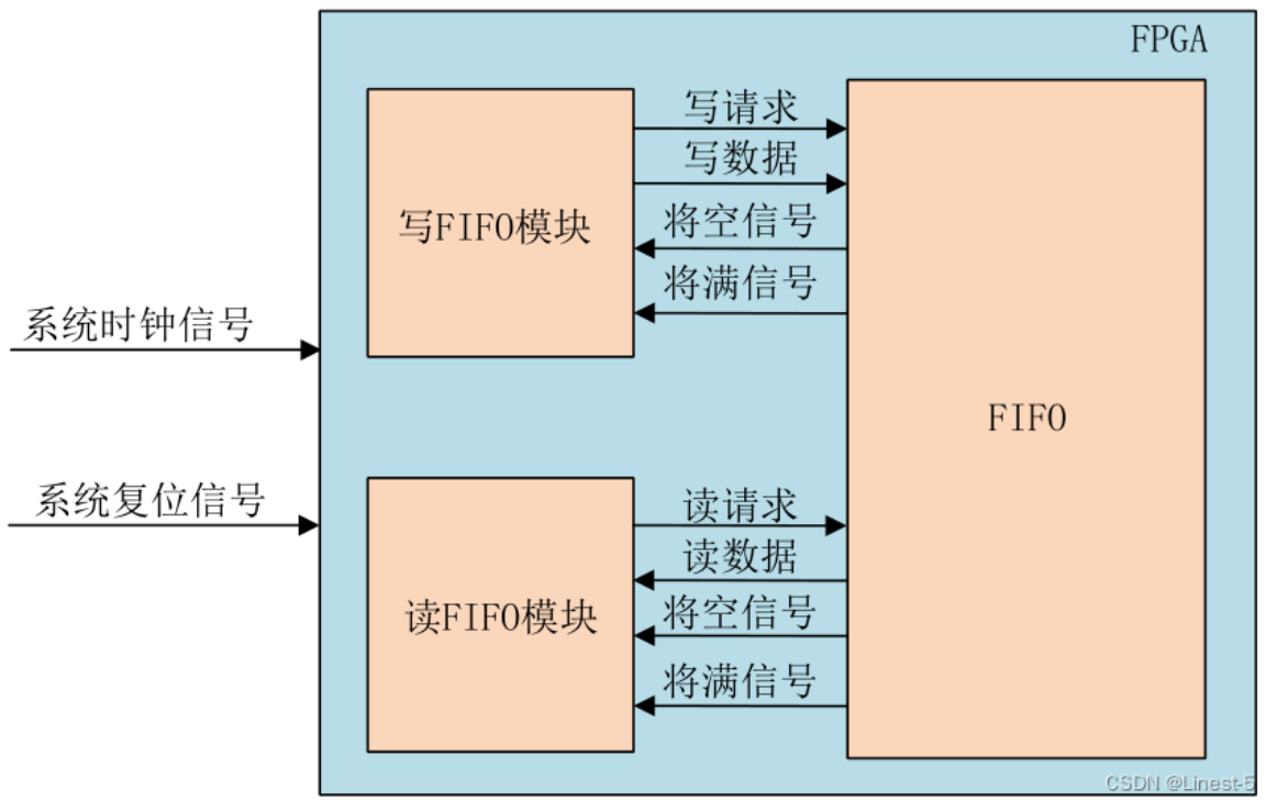
endmodule整体架构:
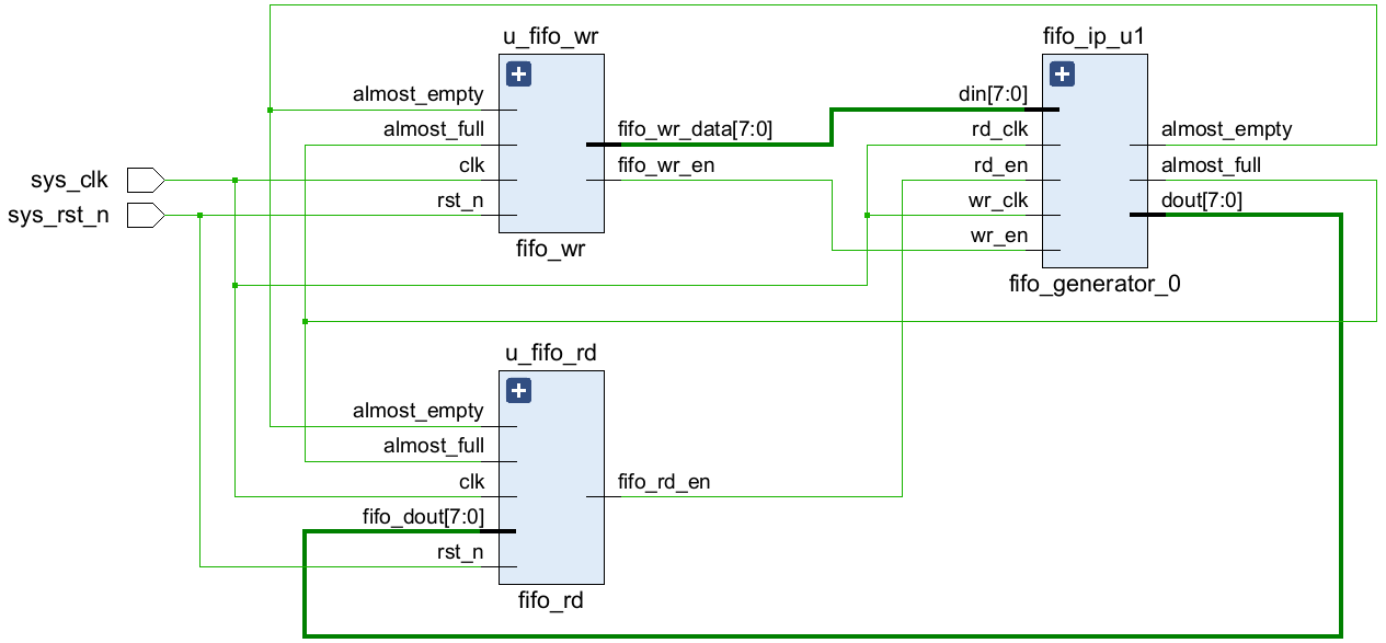
Vivado中的RTL视图:
3.Testbench
ip_fifo_tb.v
1
2
3
4
5
6
7
8
9
10
11
12
13
14
15
16
17
18
19
20
21
22
23
24
25
26
27
28
29
30
31
32
33
module ip_fifo_tb;
// Inputs
reg sys_clk;
reg sys_rst_n;
// Instantiate the Unit Under Test (UUT)
ip_fifo u_ip_fifo (
.sys_clk (sys_clk),
.sys_rst_n (sys_rst_n)
);
//Genarate the clk
parameter PERIOD = 20;
always begin
sys_clk = 1'b0;
#(PERIOD/2) sys_clk = 1'b1;
#(PERIOD/2);
end
initial begin
// Initialize Inputs
sys_rst_n = 0;
// Wait 100 ns for global reset to finish
#100 ;
sys_rst_n = 1;
// Add stimulus here
end
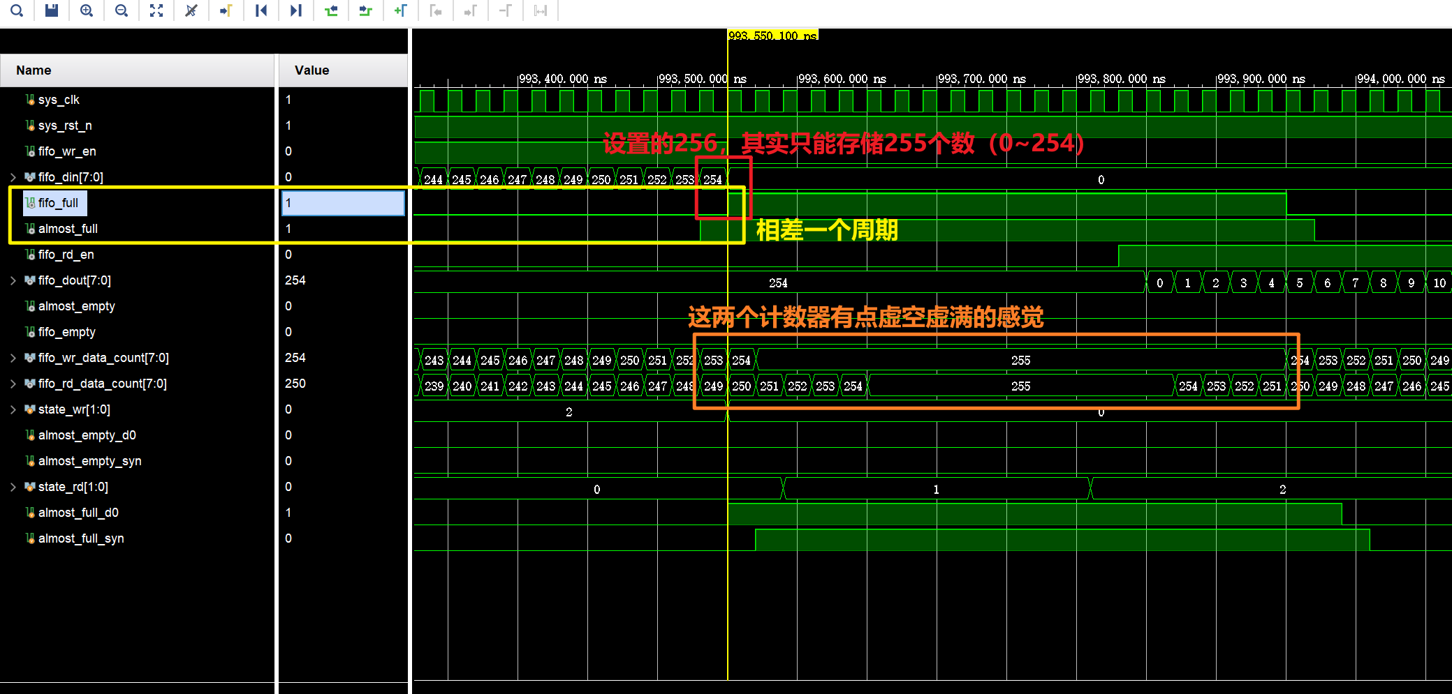
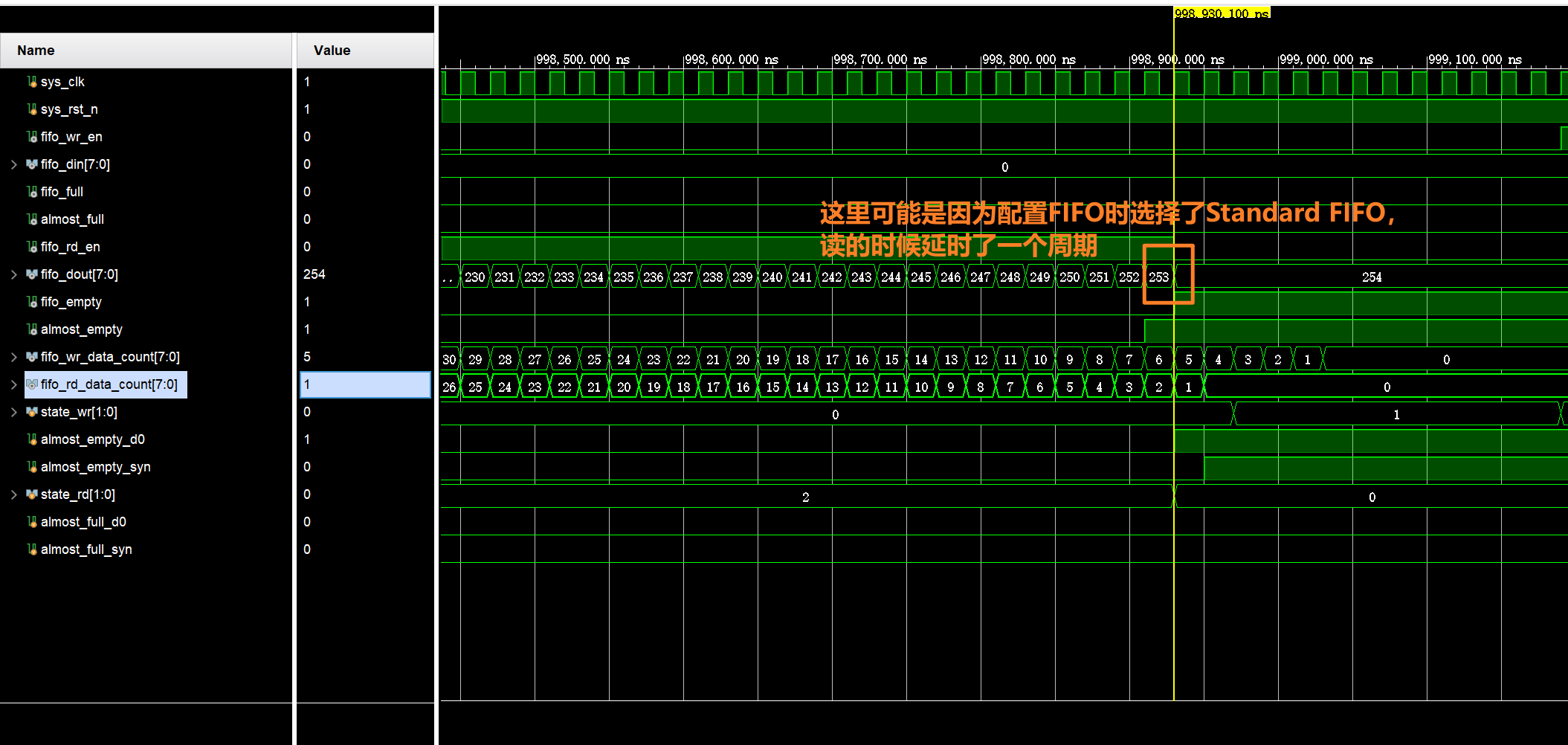
endmodule仿真结果: