本文主要利用Vivado工具,在码代码并仿真的过程中学习Verilog的知识点以及设计思路
分频计数器设计
- 将输入时钟100MHZ分频形成1MHZ
1.关键点
最大计数值CNT_MAX为$\frac{输入时钟频率}{分频得到的频率}$,计数时从0计数到CNT_MAX-1
1
2
3
4
5
6
7
8
9
//产生0~100的时钟计数器
always @(posedge clk) begin
if(!rst_n)
cnt_clk<=8'd0;
else if(cnt_clk<(`CNT_MAX-1))//从0计到99(cnt_clk为99时,其会消耗一个时钟周期回到0),故总共消耗100个时钟周期
cnt_clk<=cnt_clk+1'b1;
else
cnt_clk<=8'd0;
end- 上面代码看上去是不是像从0计数到98,但是当cnt_clk等于99时,也会进入这段代码,只是之后cnt_clk的值变为了0,故实际上这段代码是从0计数到99
产生分频时钟,计数为0-49时为高电平,计数为50-99时为低电平
1
2
3
4
5
6
7
8
9
//产生1MHZ的时钟
always @(posedge clk) begin
if(!rst_n)
clk_1mhz<=1'b0;
else if(cnt_clk<`CNT_MAX_div2)//从0计到49,总共花费50个时钟周期
clk_1mhz<=1'b1;
else
clk_1mhz<=1'b0;
end- 上述分频时钟的产生实际上会比计数器的产生延时一个系统时钟周期,因为计数器cnt_clk在时钟上升沿变化时,不会被立马捕捉到,只有在再下一个时钟周期时,才能捕捉到变化后的值
2.源代码
1 |
|
3.Testbench
1 |
|
4.仿真结果


- 由仿真结果可以很明显看到cnt_clk是从0-99计数,且输出的分频时钟延时了一个周期,看上去是从1-50为高电平
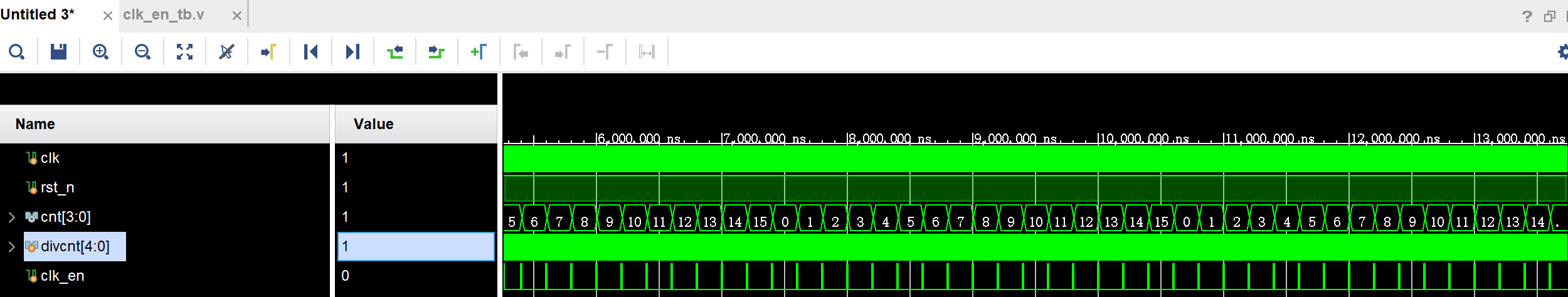
使能时钟设计
- 输入时钟100MHz,产生一个5MHz的时钟使能信号,并使能此时钟使能信号进行0~15的周期计数
1.关键点
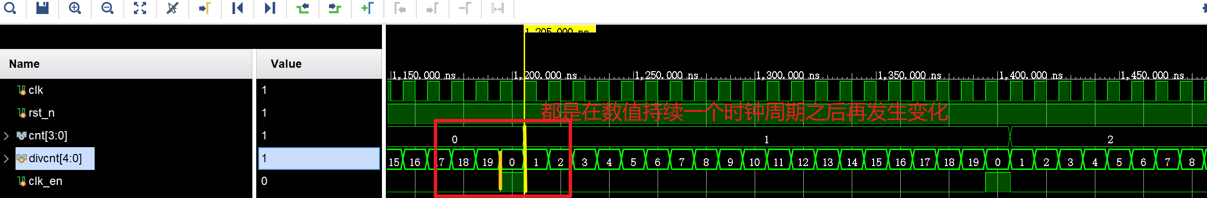
时钟使能信号只是持续了一个时钟周期,故用
divcnt==(DIVCNT_MAX-1)来判断是否拉高时序逻辑中,数据变化时,其他模块获取不到该数据变化的值,只有在下一个时钟周期时才能获取变化后的值,也就是相应数据的变化会在对应数据持续一个时钟周期之后再改变
2.源代码
1 | module clk_en( |
3.Testbench
1 |
|
4.仿真结果
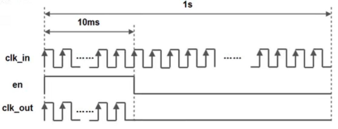
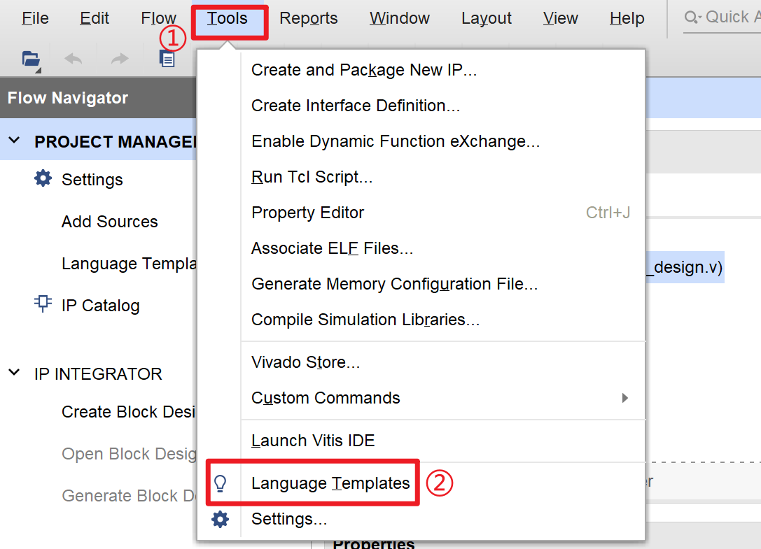
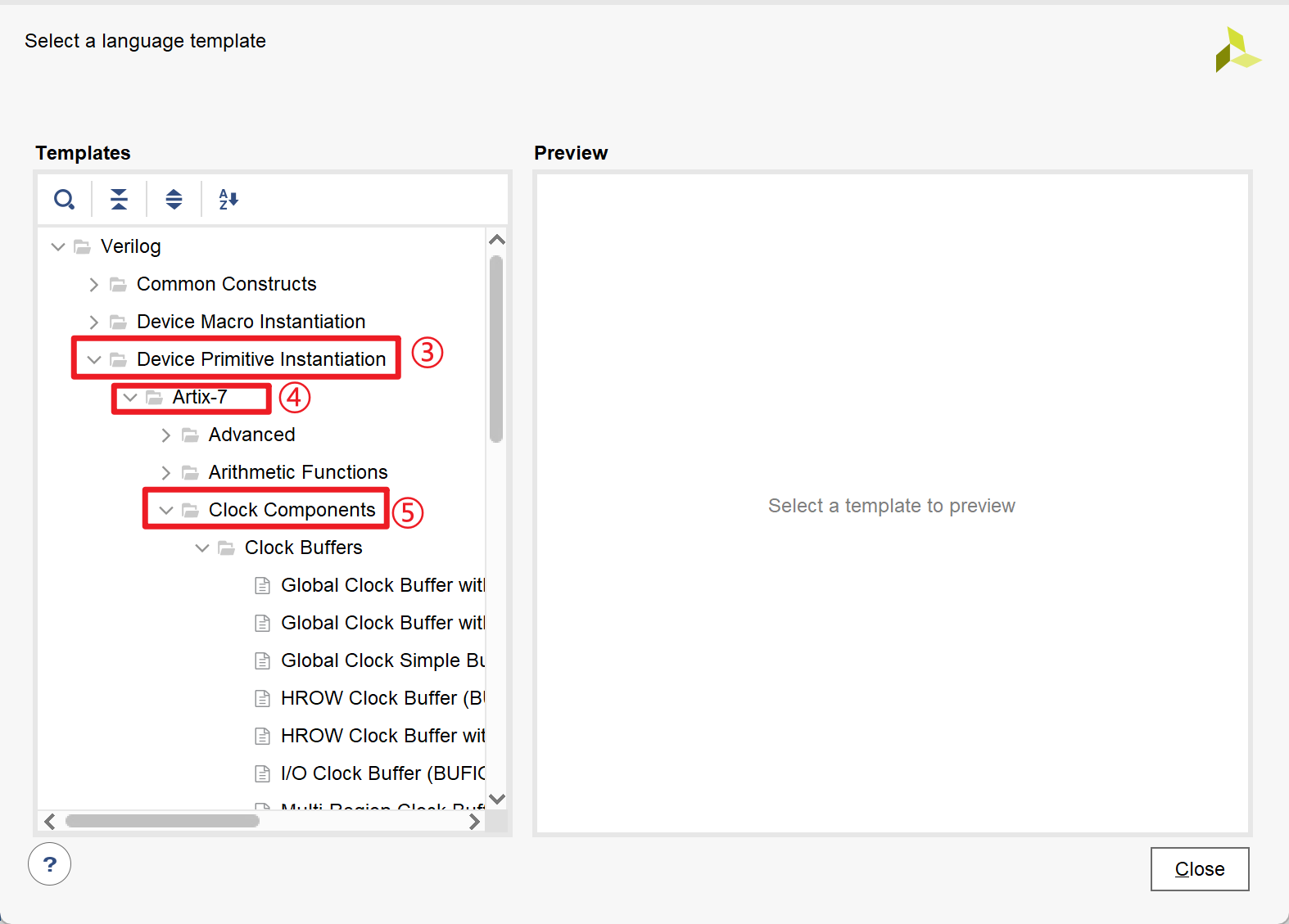
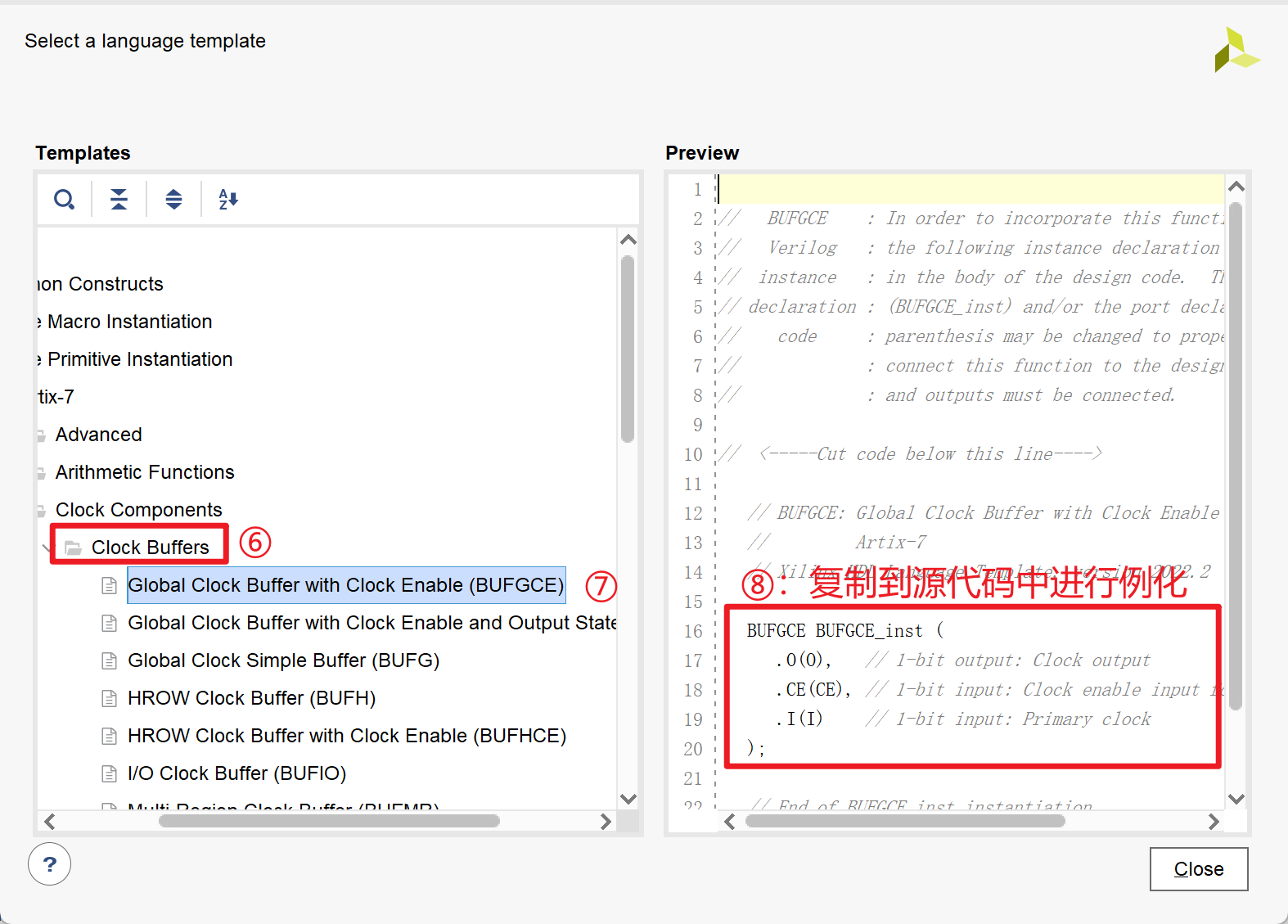
基于Xlinx BUFGCE原语的门控时钟设计
- FPGA系统时钟100MHz,系统每秒进行一次数据采集与处理,每次维持10ms,其余时间空闲,在空闲时间内希望关闭100MHz的工作时钟
1.关键点
BUFGCE原语的例化
利用define、ifdef、endif语句方便仿真测试
1
2
3
4
5
6
7
8
9//在真实情况下运行时,将此行注释掉就行
//仿真情况下用较小的计数值代替,不然仿真时间过长
localparam TIMER_CNT_1s = 30'd1_000-1'b1;//1s计数的最大值
localparam TIMER_CNT_10ms=30'd1_0-1'b1;//10ms计数的最大值
localparam TIMER_CNT_1S = 30'd100_000_000-1'b1; //1s计数的最大值
localparam TIMER_CNT_10MS = 30'd1_000_000-1'b1; //10ms计数的最大值
2.源代码
1 | module BUFGCE_design( |
3.Testbench
1 |
|
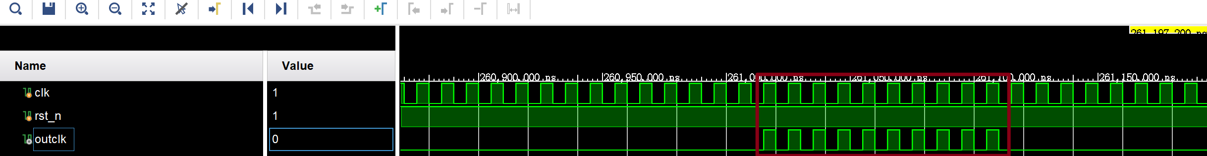
4.仿真结果
同步复位与异步复位
1.关键点
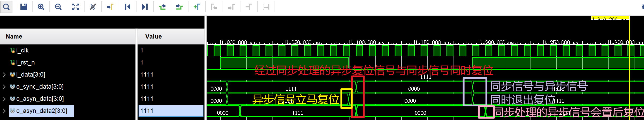
- 经过同步处理的异步复位信号与同步信号受到时钟控制会同时复位,异步信号会不受时钟控制立马复位
- 同步信号与异步信号同时退出复位,同步处理的异步信号会置后一个时钟周期后退出复位
2.源代码
1 |
|
3.Testbench
1 |
|
4.仿真结果
脉冲边沿检测
1.关键点
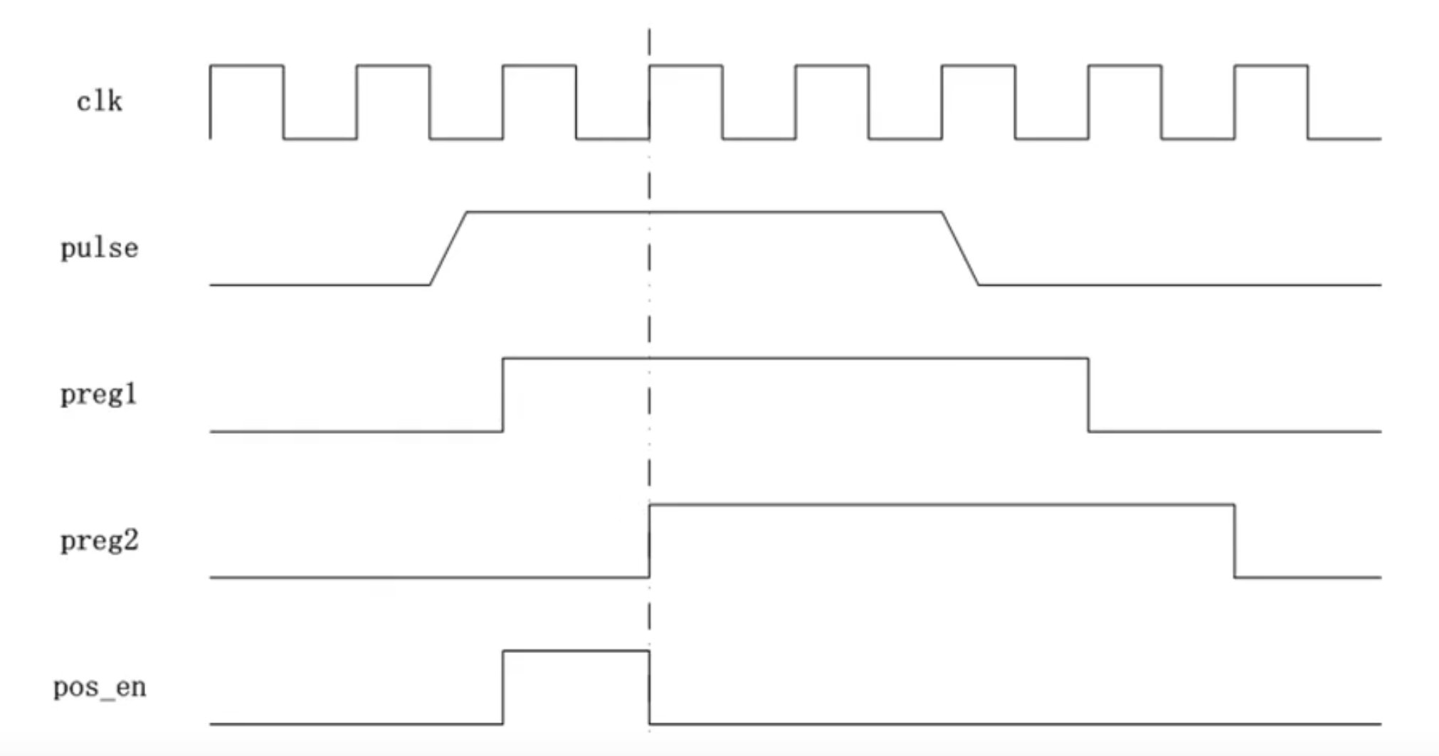
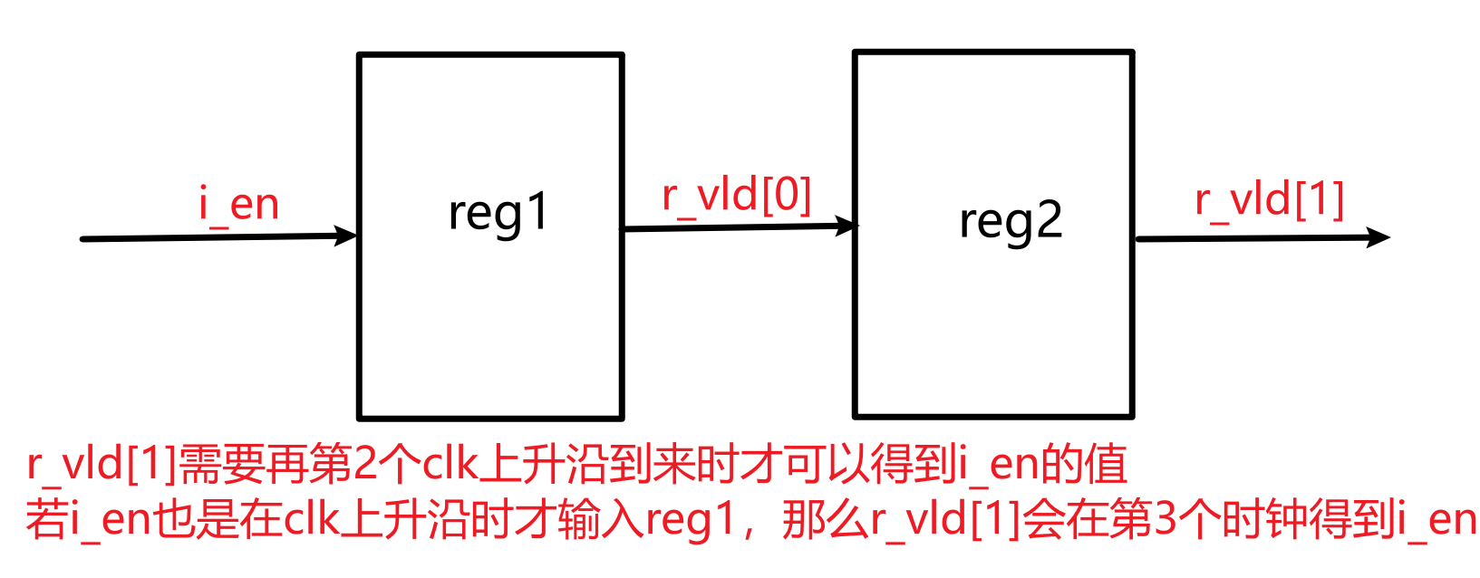
- 使用两级寄存器对输入脉冲进行缓存,低位寄存器保存的是最新输入数据,而高位寄存器保存的是低位寄存器的数据,故高位寄存器比低位寄存器慢一个时钟周期
关键代码:
1
2
3
4
5
6
7
8
9
10
11
reg [1:0] r_pulse;//两级寄存器
always @(posedge i_clk) begin
if(!i_rst_n)
r_pulse<=2'b00;
else
r_pulse<={r_pulse[0],i_pulse};
//上述代码等效为:
//r_pulse[0]<=i_pulse;
//r_pulse[1]<=r_pulse[0];
end
2.源代码
1 |
|
3.Testbench
1 |
|
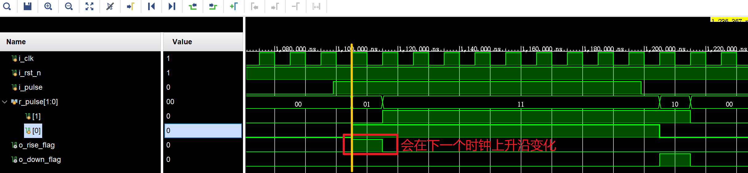
4.仿真结果
脉冲计数器
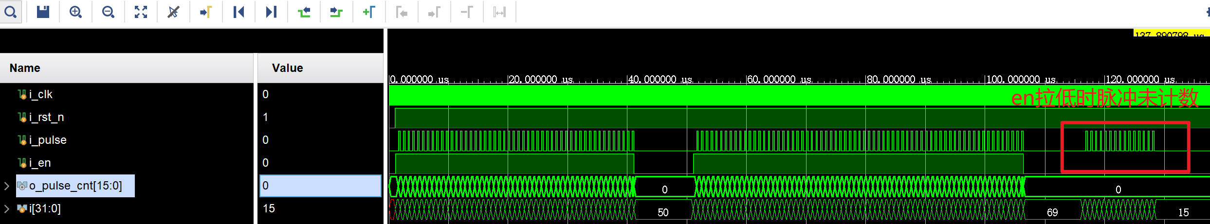
- 在使能信号高电平进行计数,在低电平对计数清零
1.源代码
1 |
|
2.Testbench
1 |
|
3.仿真结果
generate语法的使用
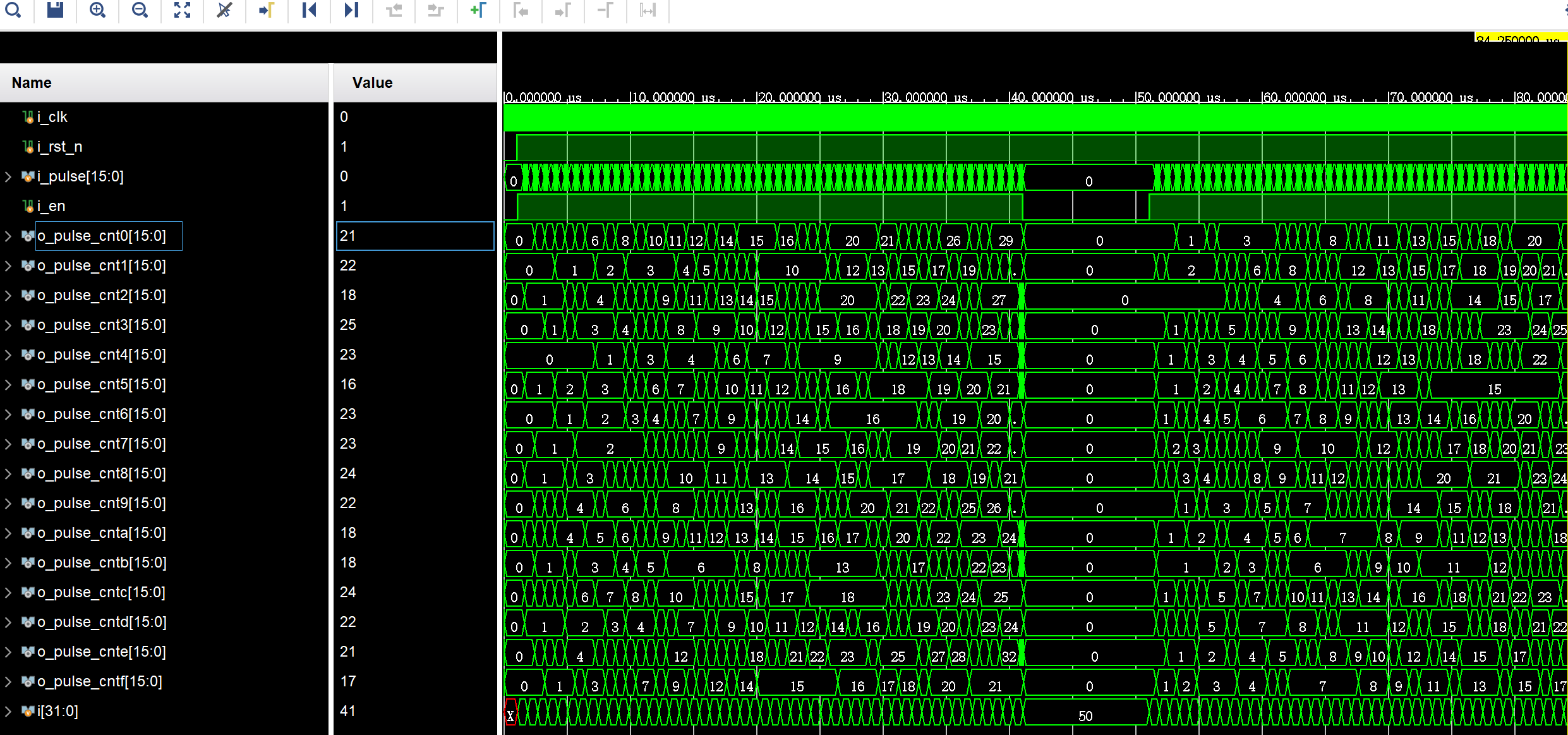
设计一个脉冲计数器,功能如下:
输入脉冲:16路脉冲信号,分别对每路进行脉冲检测并计数
使能信号:高电平进行计数,低电平清零计数器
1.关键点
- generate语法有generate for、generate if和generate case三种,可以在generate中使用的语法语句包括module、UDP(用户自定义原语)、门级原语、连续赋值语句assign、always语句和initial语句等
- 定义genvar作为generate我的循环变量
- 随机数的产生:
{$random}%65536;//产生0~65535的随机数,若不加括号,即为$random%65536,则产生-65535-+65535之间的随机数
2.源代码
1 | module generate_for_design( |
3.Testbench
1 |
|
4.仿真结果
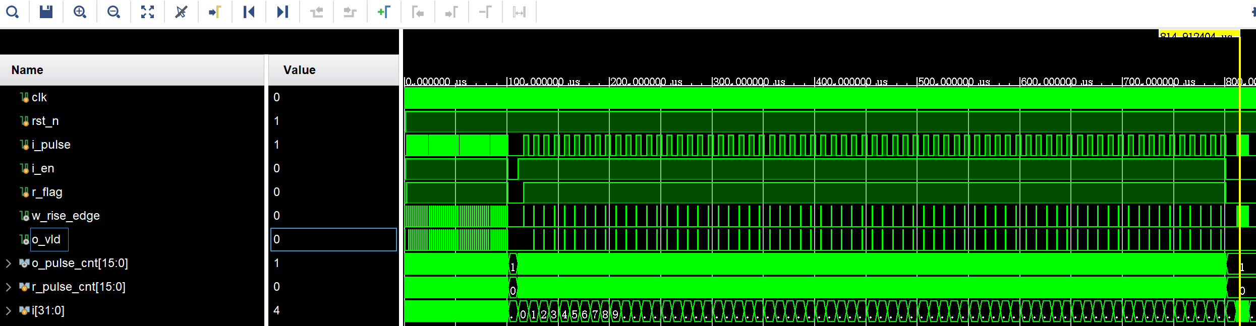
频率计数器
- 在使能信号控制下,计算输入脉冲的每两个上升沿之间的时钟周期数并输出,即输出脉冲频率的计数值
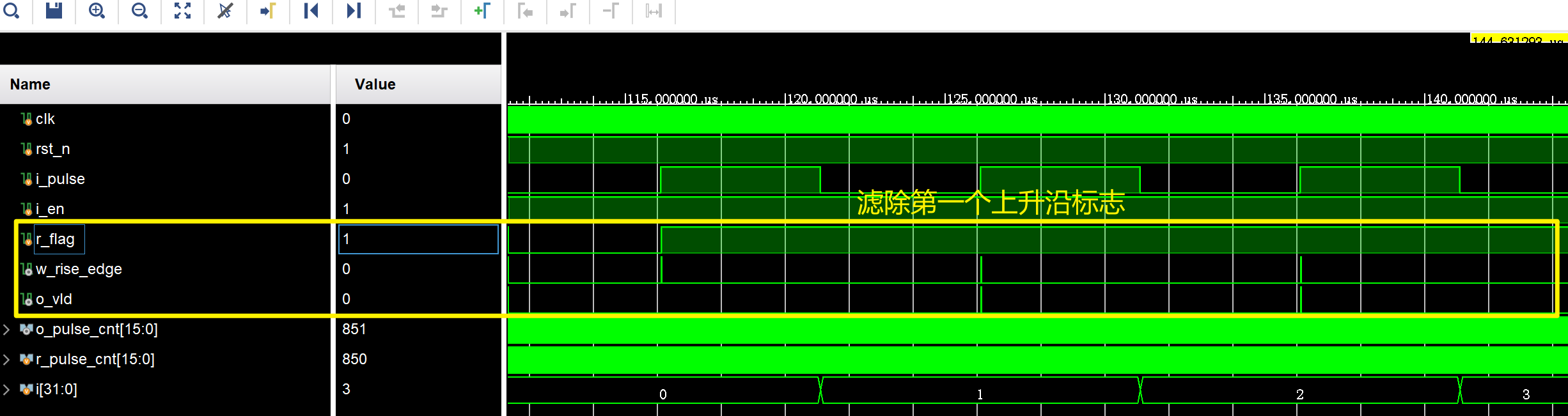
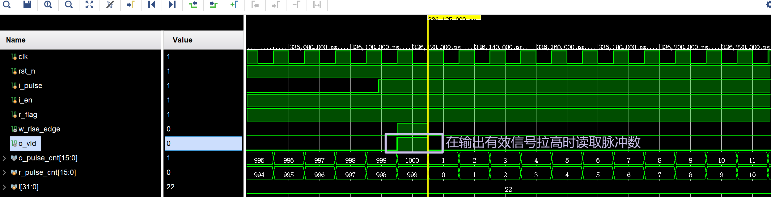
1.关键点
遇到上升沿检测标志就读取脉冲数
但是要滤除第一个上升沿检测标志,因为这时候刚刚使能,读取的第一个上升沿并不是两个上升沿之间的读数,滤除方式如下:
1
2
3
4
5
6
7
8
9
10
11
12
13
14
15
16
//////////////////////////////////////////
//输出信号产生:需要滤除第一个w_rise_edge脉冲信号
reg r_flag;
always @(posedge i_clk) begin
if(!i_rst_n)
r_flag <= 'b0;
else if(!i_en)
r_flag <= 'b0;
else if(w_rise_edge)
r_flag <= 'b1;
else
r_flag<=r_flag;
end
assign o_vld = w_rise_edge & r_flag;因为计数值是从0开始计数,故输出计数值时需要加1
2.源代码
1 | module frequency_counter_design( |
3.Testbench
1 |
|
4.仿真结果
4位格雷码计数器
1.关键点
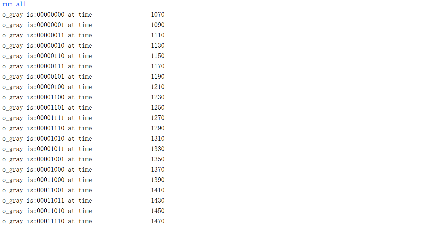
- 系统显示任务
$display和$write$display在一次输出后自动换行,而$write则不会- 默认情况下,输出显示的数值所占字符个数由输出信号的数值类型和位宽决定。
- 用十进制显示时,高位的0会默认以空格填充,而用其他进制显示时,高位的0会显示出来。
- 在“%”和格式字符之间可以添加数字0,可以隐藏前置的0或空格,使得第一个非0数字顶格显示
- 监视任务
$monitor- 当监视的信号发射变化时,会打印当前的值,通常与时间戳
$time配合使用 $monitoroff关闭监视$monitoron打开监视
- 当监视的信号发射变化时,会打印当前的值,通常与时间戳
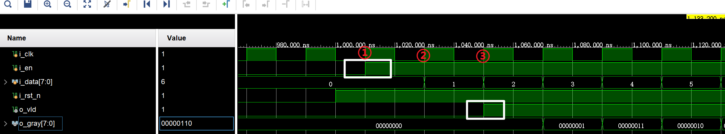
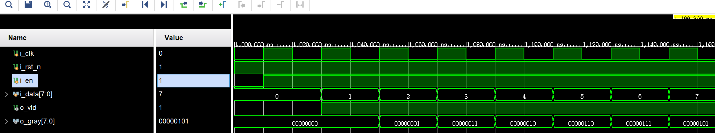
- 在always语句块中使用case语句描述组合逻辑,再使用assign将r_gray赋值给o_gray
2.源代码
1 | module gray_counter_design( |
3.Testbench
1 |
|
4.仿真结果
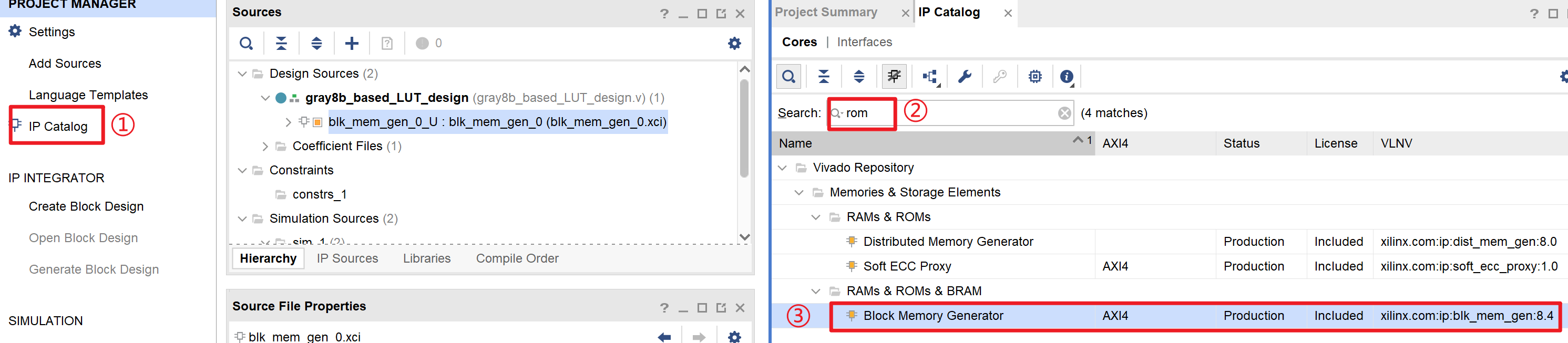
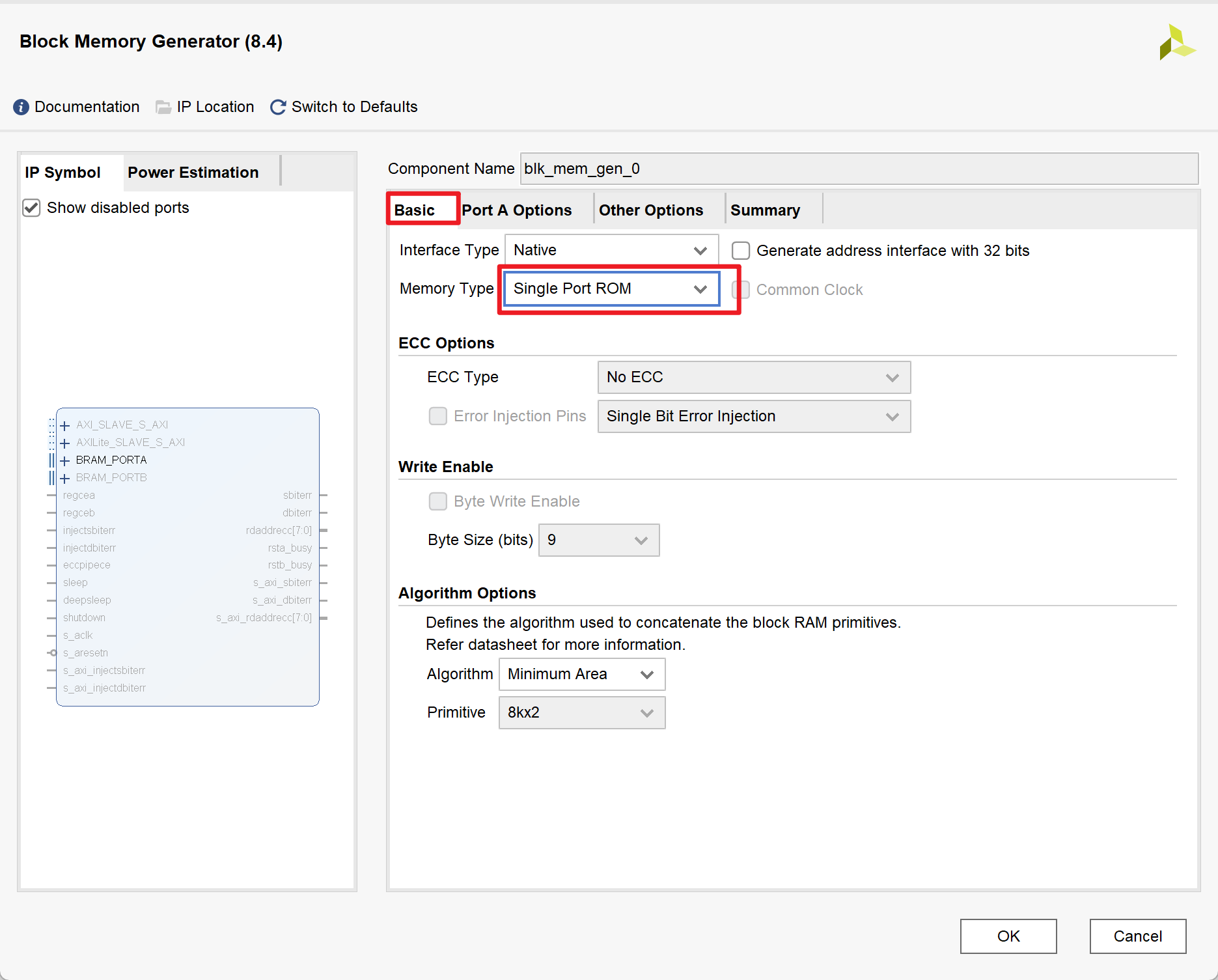
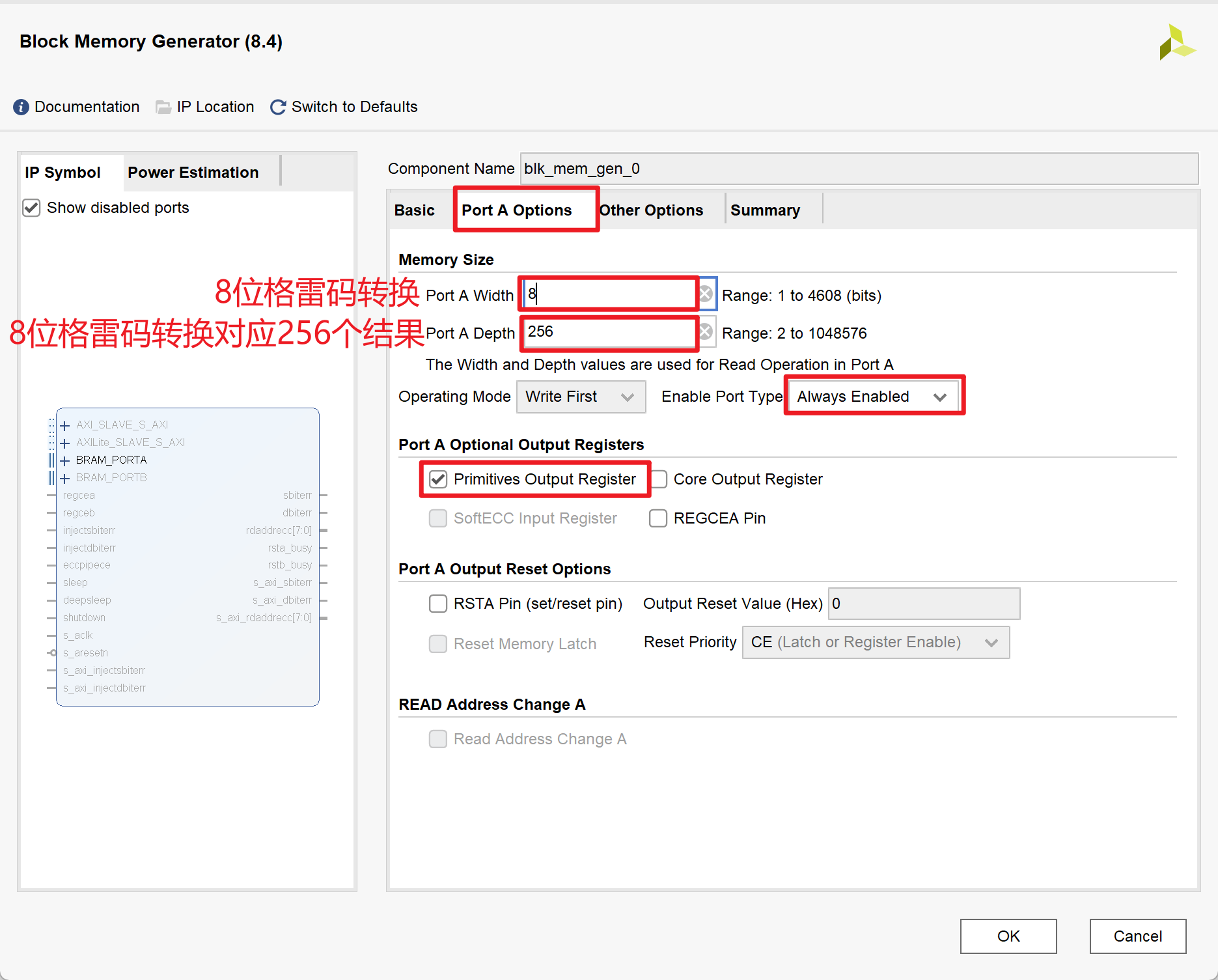
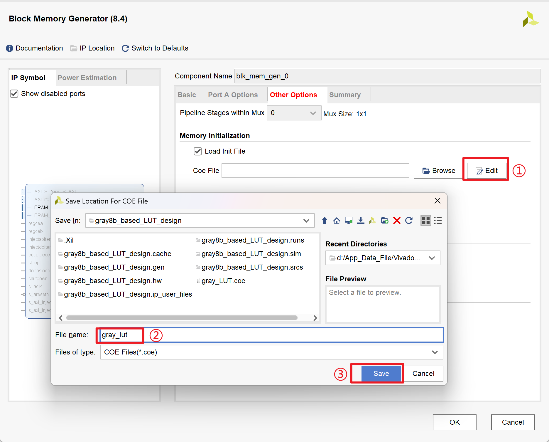
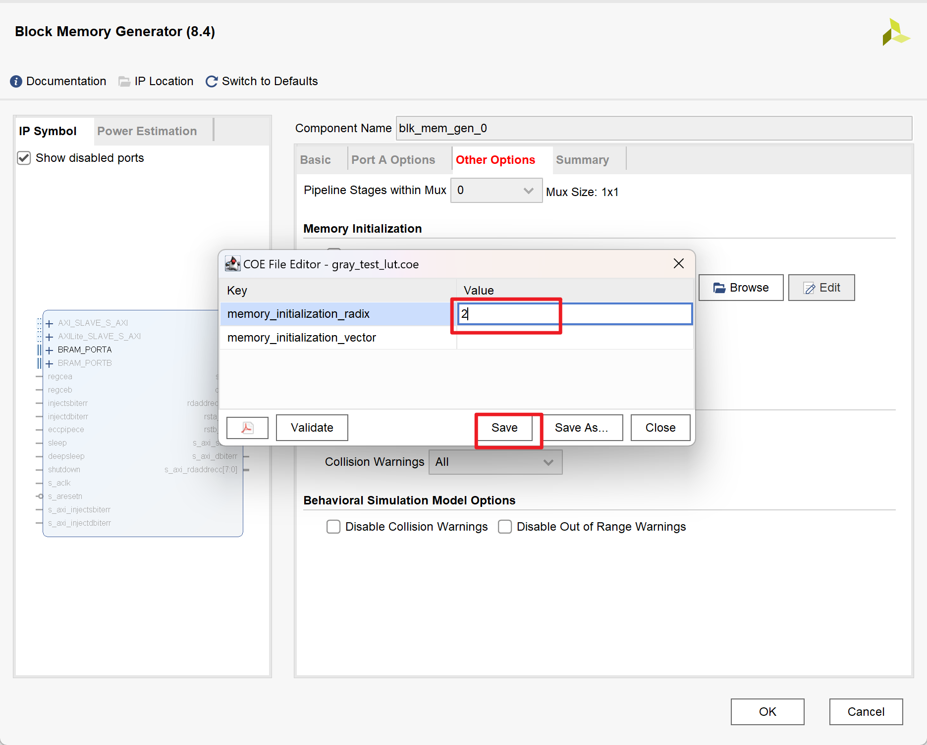
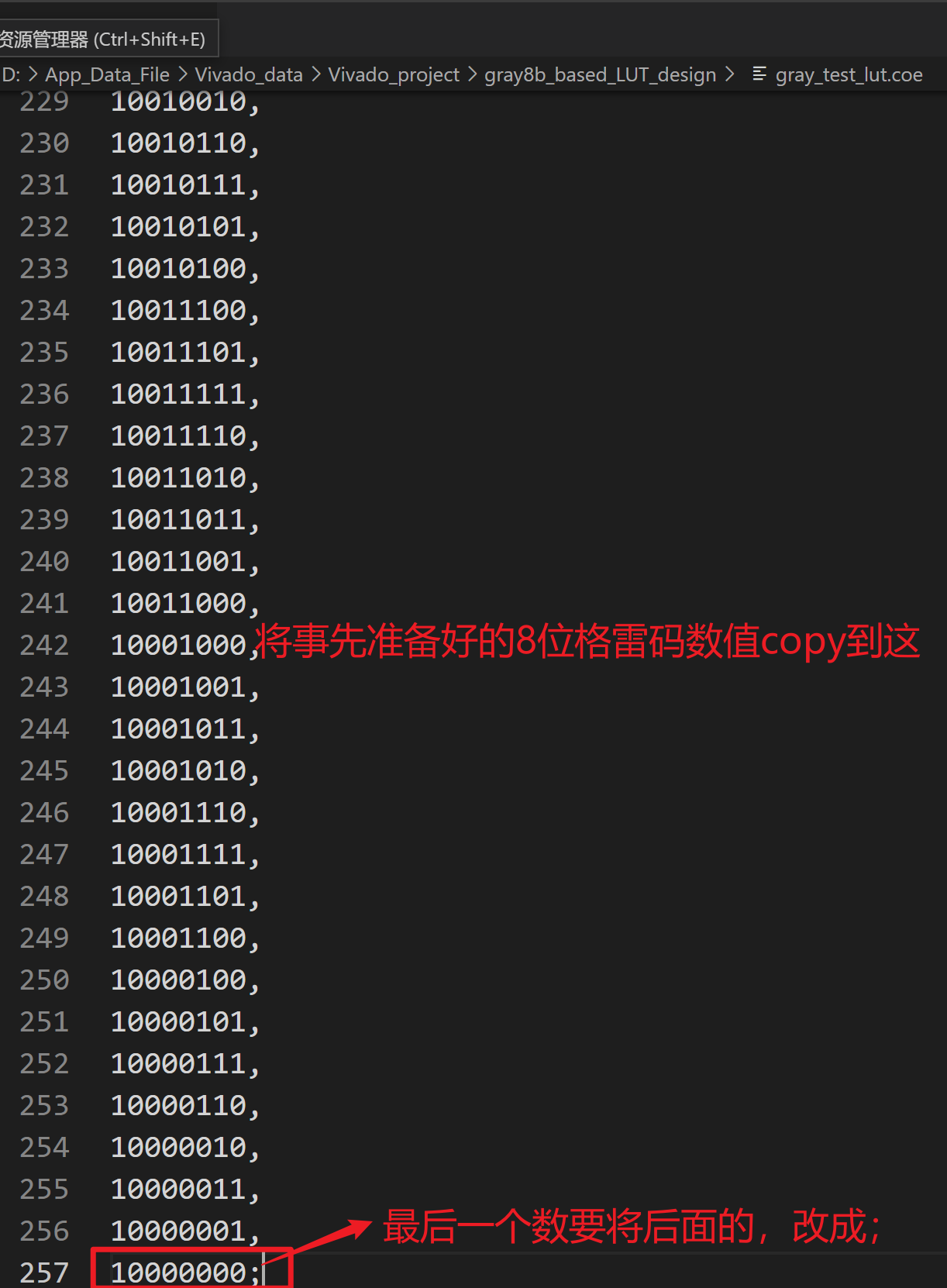
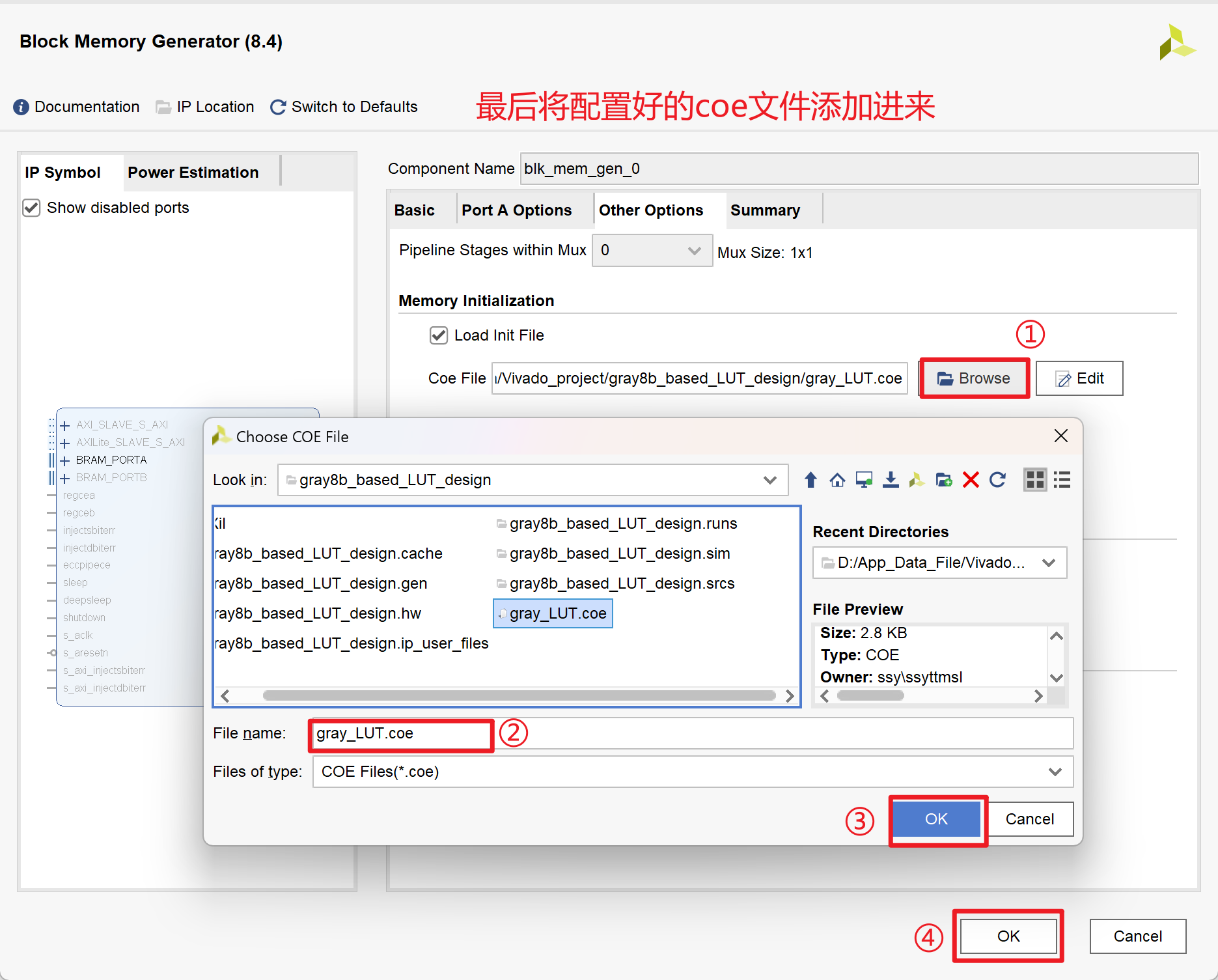
基于查找表的8位格雷码转换
1.关键点
查找表
- 查找表简单说就是一个预先存储好结果的数据表
- 通过访问这张预先存储好结果的数据表,可以快速的获取不同输入的输出结果
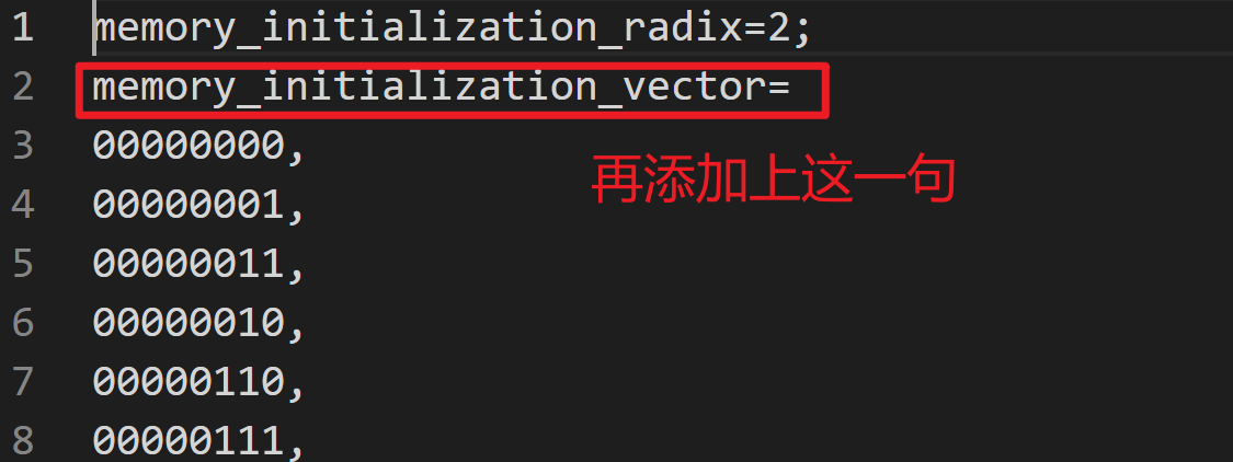
ROM初始化COE文件制作
打拍操作:其类似脉冲边沿检测
2.源代码
1 | module gray8b_based_LUT_design( |
3.Testbench
1 |
|
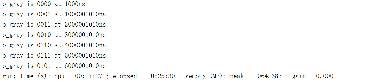
4.仿真结果
格雷码转换的快速算法
1.关键点
二进制码的最高位直接赋值给格雷码的最高位
对于次高位到最低位,使用二进制码相邻位异或的方式获取:
- 若二进制码字的第i位和i+1位相同,则第i位的格雷码为0
- 若二进制码字的第i为和i+1位不同,则第i位的格雷码位1
用generate语法实现异或处理
1
2
3
4
5
6
7
8
genvar i;
generate
for(i=MSB-1;i>=0;i=i-1) begin
always @(posedge i_clk) begin
o_gray[i]<=i_data[i]^i_data[i+1];
end
end
endgenerate
2.源代码
1 | module grayCode_quickMethod_design #( |
3.Testbench
1 |
|
4.仿真结果
Testbench中文本文件写入操作
1.关键点
$fopen的用法文件描述符=$fopen("文件名","文件操作类型")- 文件操作类型:
“r”:读取文件“w”:写入文件“a”:在文件末尾追加文件
$fclose的用法$fclose("文件描述符")
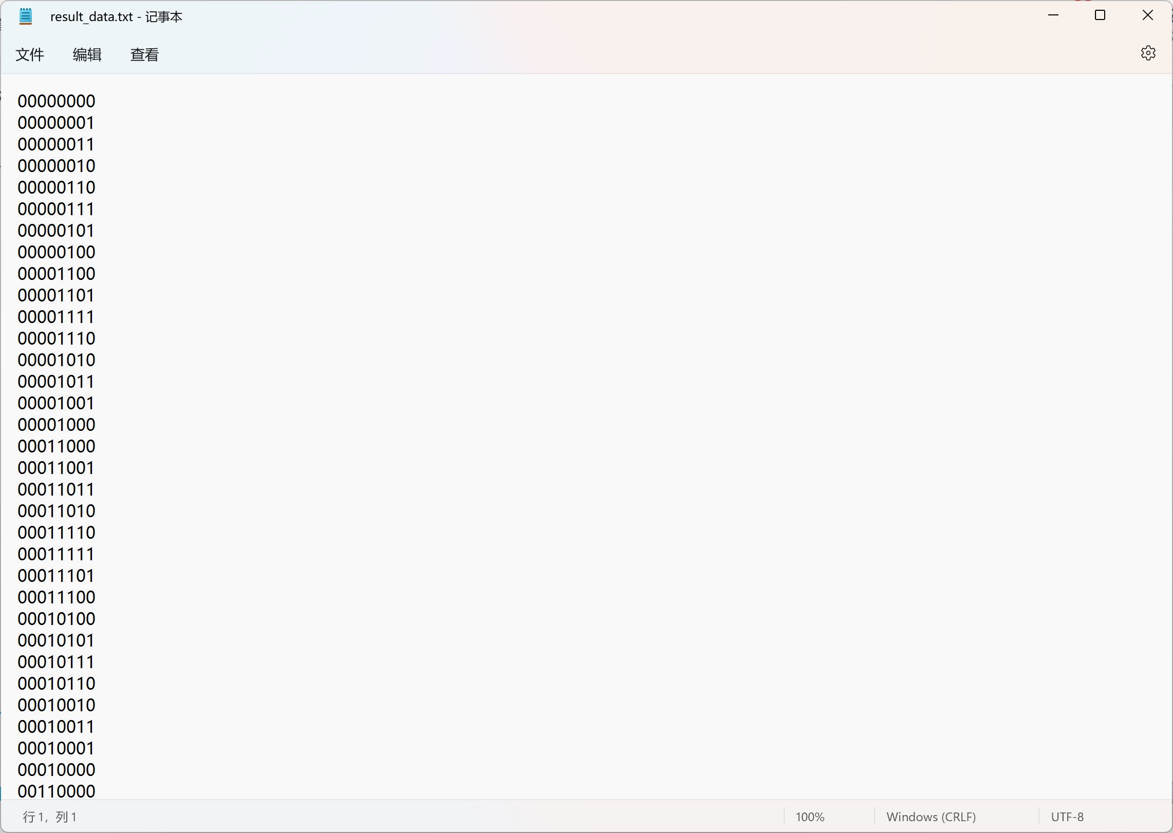
$fwrite的用法$fwrite("文件描述符","字符串与数据格式",变量)
2.源代码
1 | module gray8b_based_LUT_design( |
3.Testbench
1 |
|
4.仿真结果
Testbench中文本文件读取操作
1.关键点
- 十六进制文件读取$readmemh:
$readmenh("文件名",存储器名,起始地址,结束地址) - 二进制文件读取$readmemb:
$readmenb("文件名",存储器名,起始地址,结束地址)
2.源代码
1 | module gray8b_based_LUT_design( |
3.Testbench
1 |
|
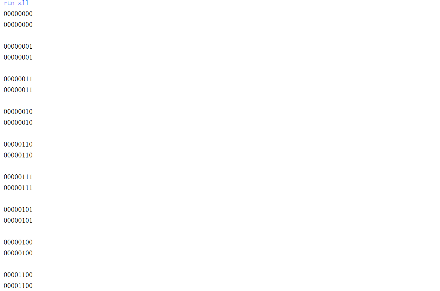
4.仿真结果
基于随机数的自动化仿真测试
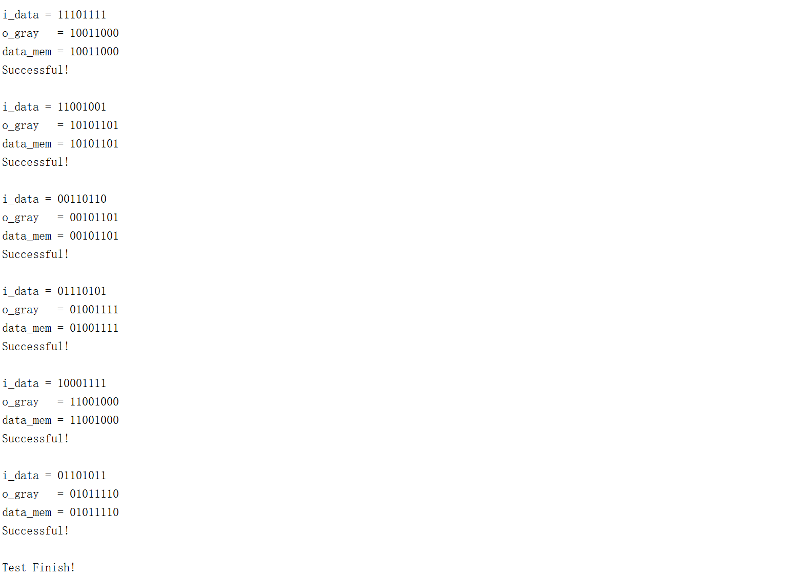
- 通过自动生成随机数测试格雷码转换的快速算法模块是否正确
1.关键点
$random(seed)$random表示产生一个32位的随机数,如果不设置seed,每次取得的随机数是相同的
{$random}%65536;//产生0~65535的随机数,若不加括号,即为$random%65536,则产生-65535-+65535之间的随机数rand=min+{$random}&(max-min+1)产生一个在min-max之间的随机数因为格雷码快速算法要延后一个时钟周期才能计算出结果,故对文件中的数据寻址时寻址地址也要延迟一个时钟周期
1
2
3
4
5reg[7:0] r_data;//用r_data作为寻址地址
always @(posedge i_clk) begin
r_data <= i_data;
end
2.源代码
1 | module gray8b_based_LUT_design #( |
3.Testbench
1 |
|
4.仿真结果
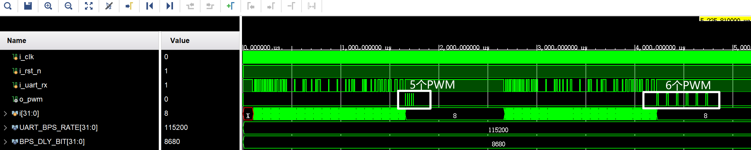
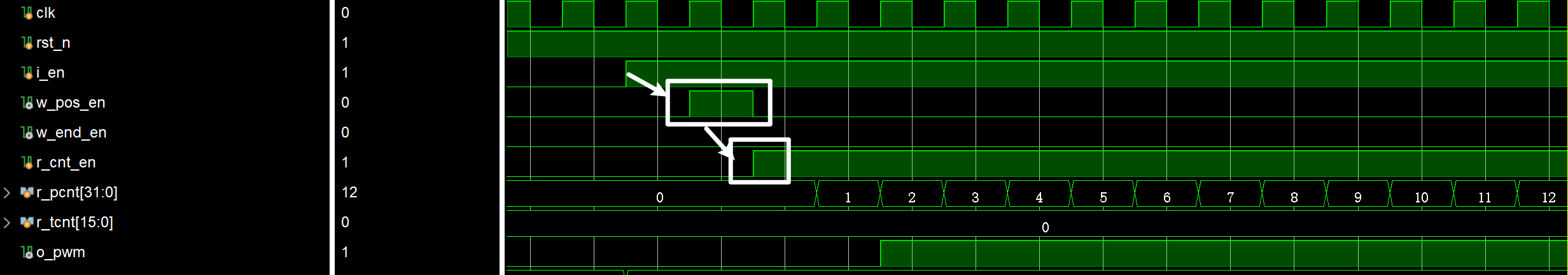
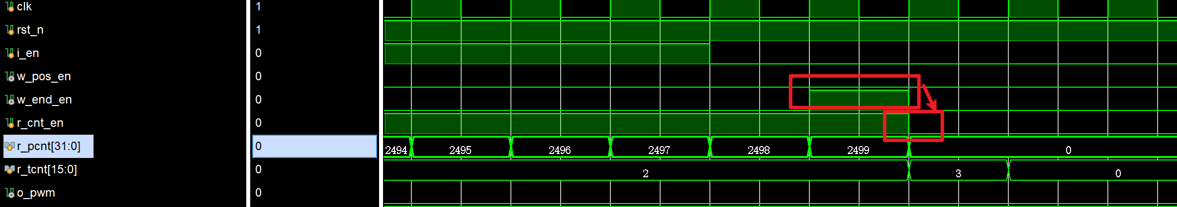
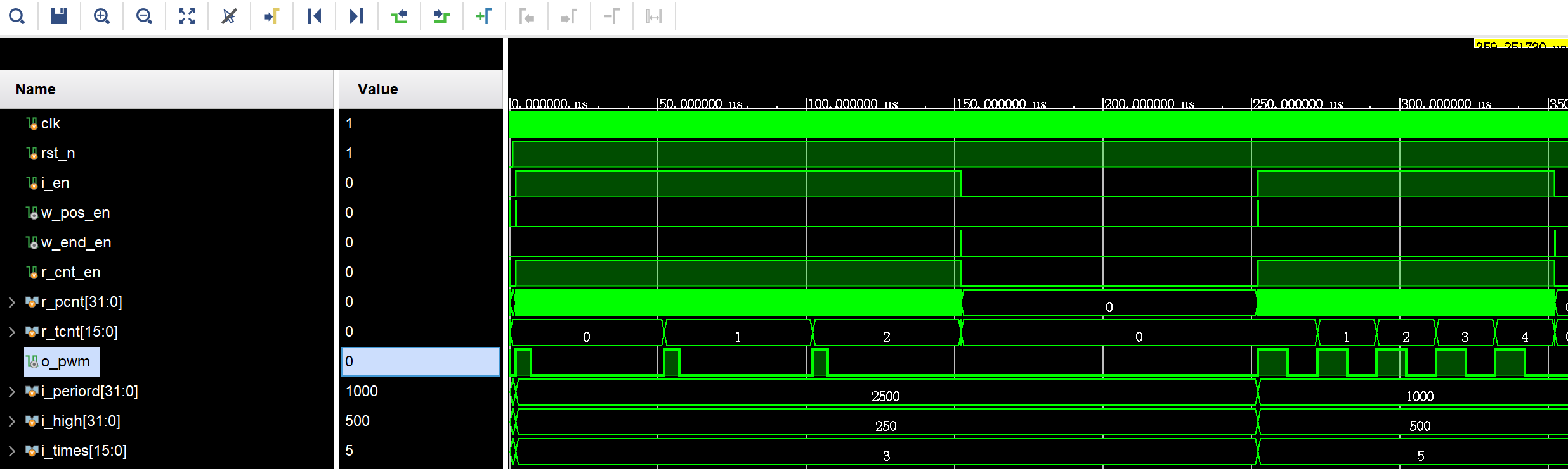
可配置的PWM设计
- PWM波的产生,有通过i_times控制产生PWM波重复的次数
1.关键点
时序分析:
- 首先需要需要i_en信号的上升沿与计数结束的标志信号w_end_en置1,从而生成控制计数器工作的使能信号r_cnt_en
- 在使能信号r_cnt_en的控制下进行PWM的周期计数,当周期计数达到其值时,次数计数加1,从而实现PWM波的次数计数
2.源代码
1 | module PWM_design( |
3.Testbench
1 | module PWM_tb; |
4.仿真结果
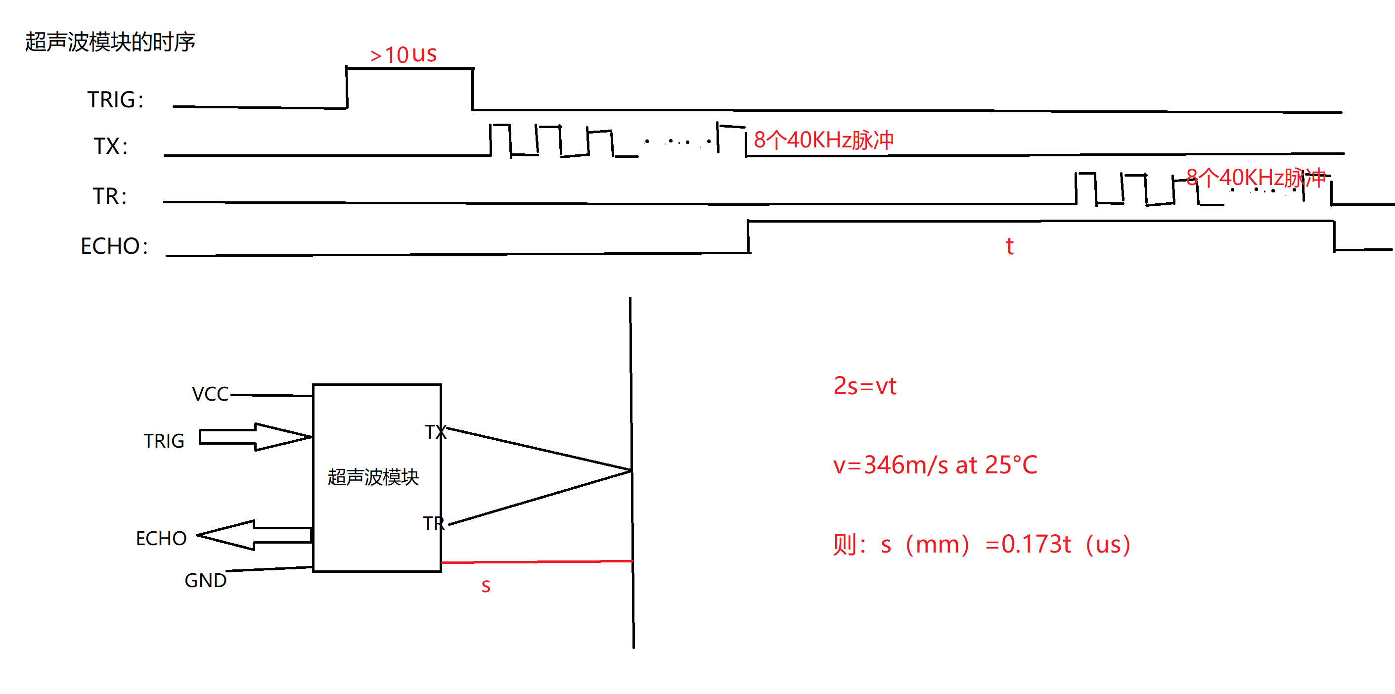
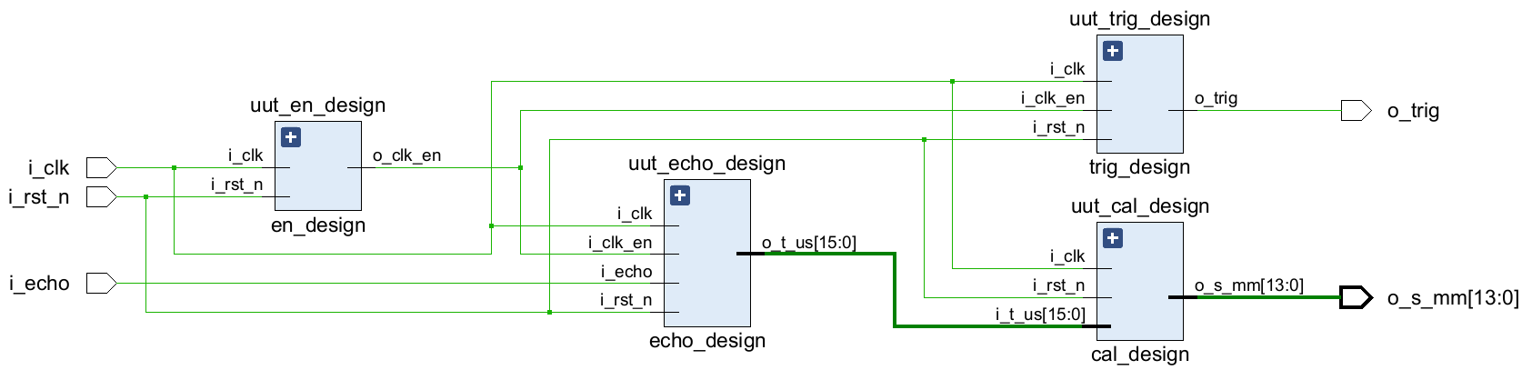
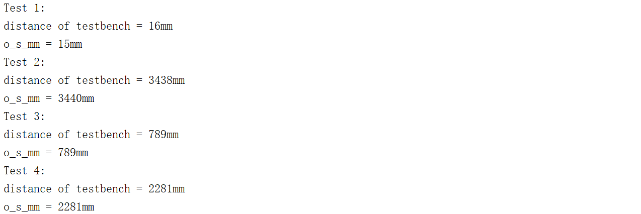
超声波测距设计
1.关键点
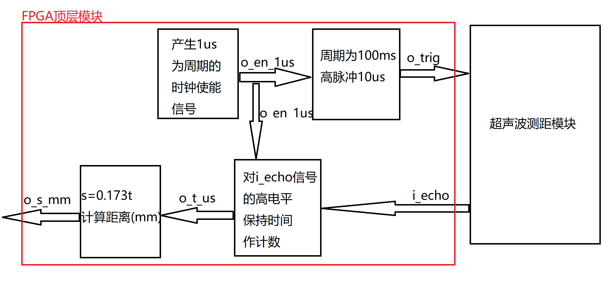
超声波测距模块原理:每隔100ms时间,定时产生10us时间的TRIG高脉冲给到超声波测距模块,用于触发超声波模块工作,通过测量ECHO端口高电平持续的时间即可得到距离信息
模块划分与接口定义:
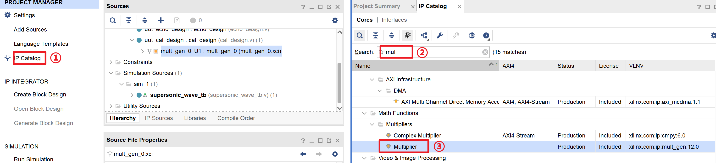
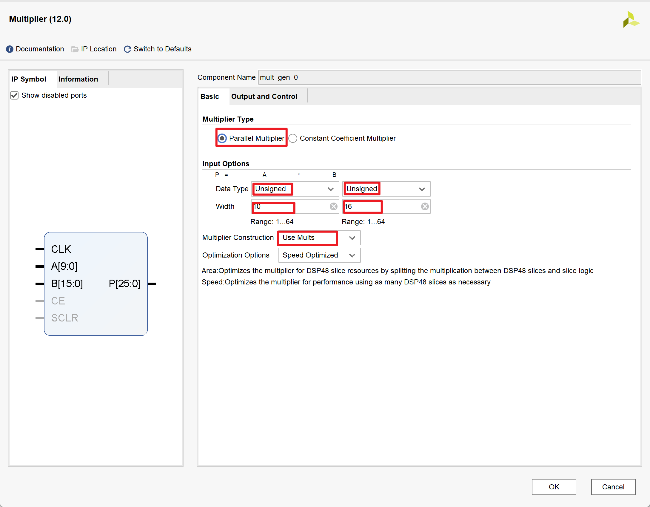
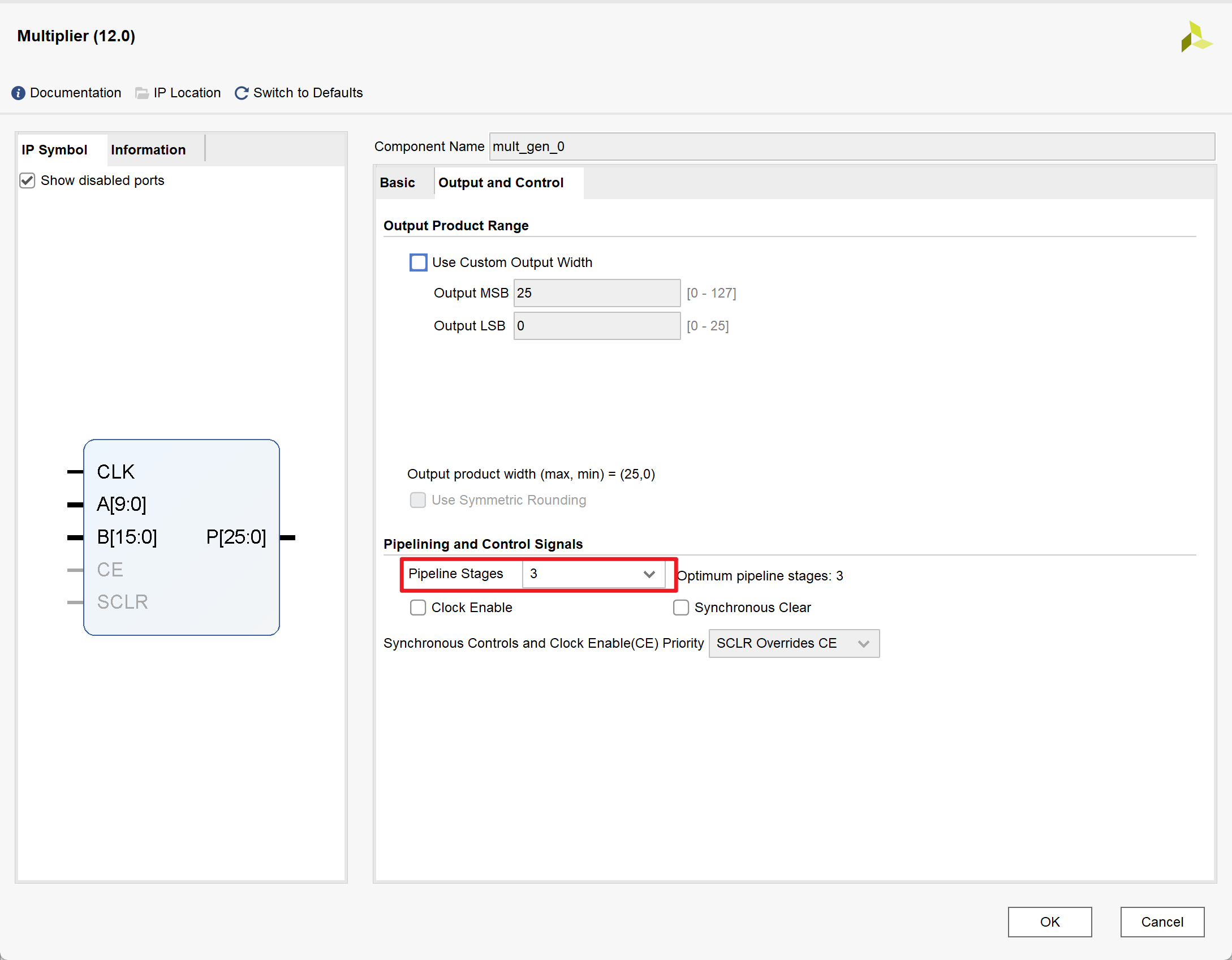
IP核实现乘法器:
2.源代码
- 顶层模块supersonic_wave_design.v
1 | module supersonic_wave_design( |
- 子模块:en_design.v
1 | module en_design #(parameter P_CLK_PERIORD = 20) |
- 子模块:trig_design.v
1 | module trig_design( |
- 子模块:echo_design.v
1 | module echo_design( |
- 子模块:cal_design.v
1 | module cal_design( |
3.Testbench
1 |
|
4.仿真结果
- RTL视图
- 打印输出的结果:
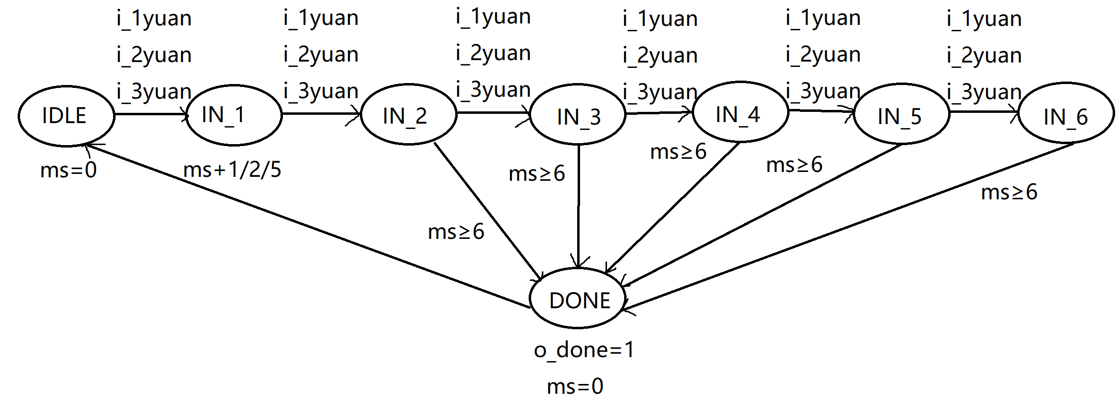
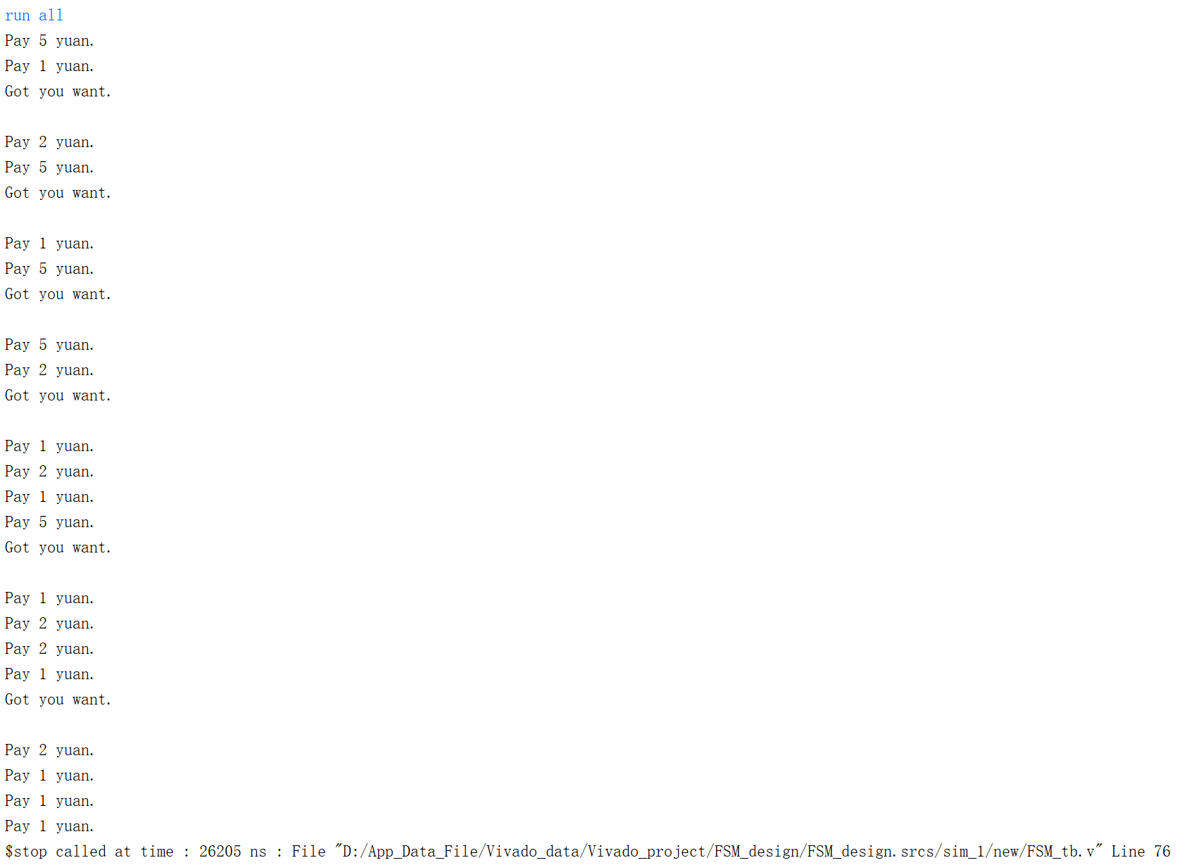
自动售卖机状态机设计
- 有纸币1/2/5,每次投一张,当总投入金额大于等于6时输出为1
1.关键点
- 状态机转换图的绘制
2.源代码
1 | module FSM_design( |
3.Testbench
1 |
|
4.仿真结果
串口指令帧解码设计
- 接收串口数据接收,串(8个1bit)转并(8bit)
译码串口(UART)命令帧,提取有效数据
- 帧头(4个字节):0xaa + 0x55 + 0xa5 + 0x5a
- 有效数据(10个字节):beep_periord(4个字节)+ beep_high(4个字节)+ beep_num(2个字节)32bit/16bit传输时,高字节在前
- 帧尾(4个字节) :0xcc + 0x33 + 0xc3 + 0x3c
按照命令控制蜂鸣器
1.关键点
UART
- UART(Universal Asynchronous Receiver/Transmitter),即通用异步收发,它的数据传输不需要时钟,只要两条信号线分别进行数据的收(RX)和发(TX)
- 收发双方首先需要约定好数据传输的速率(简单的讲就是约定好一个数据位传输的时间)和帧格式(即一帧的长短,一帧由哪些位组成,他们的功能都是什么
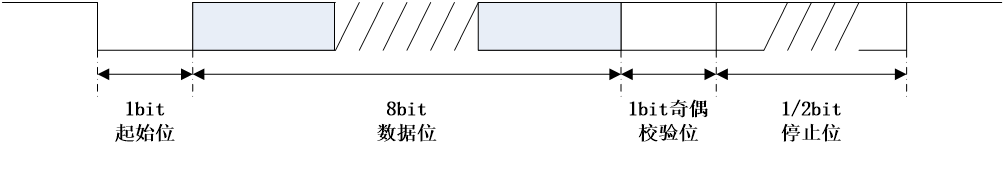
串口(UART)协议:
- 它由1个起始位(必须为0)、8个数据位(用户数据)、1个奇偶校验位(用于简单的纠错以保证传输可靠性)和1或2个停止位(必须为1)组成
- 除了奇偶校验位,其他三个部分都是必须的
- 当信号线空闲时,必须为高电平
- 要发起数据传输时,1个低电平的脉冲表示起始位,然后连续传输8个数据位和若干个高电平的停止位
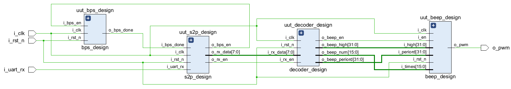
模块划分与接口定义:
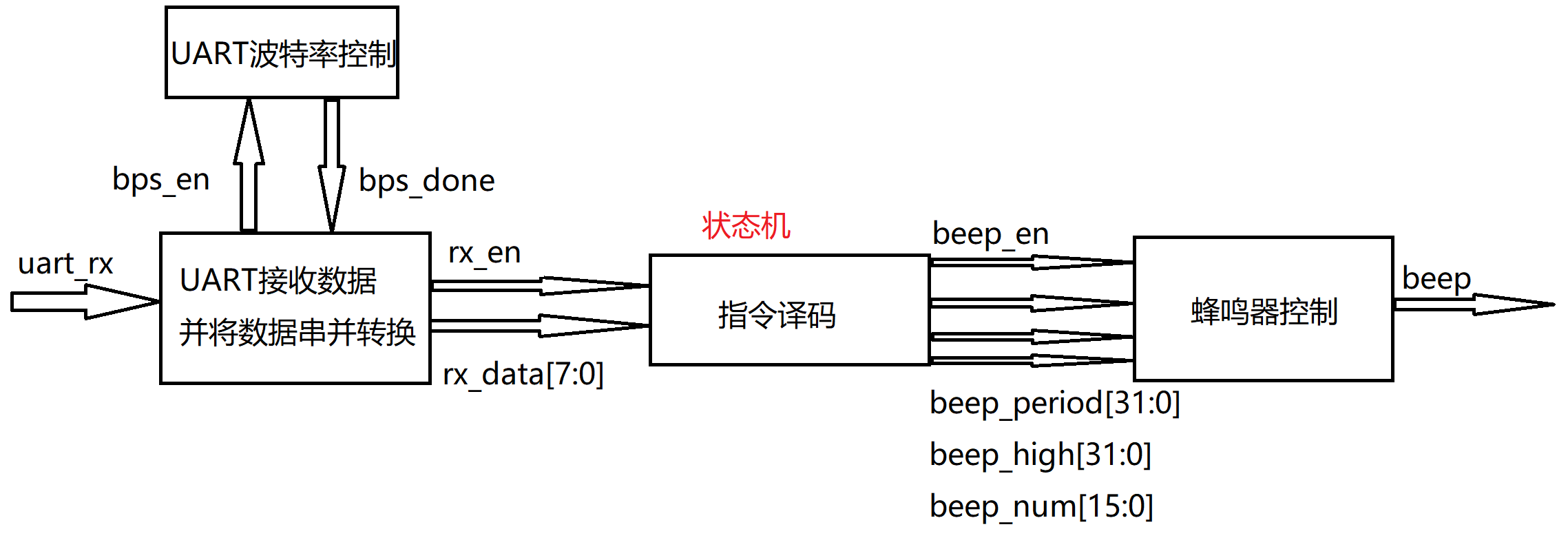
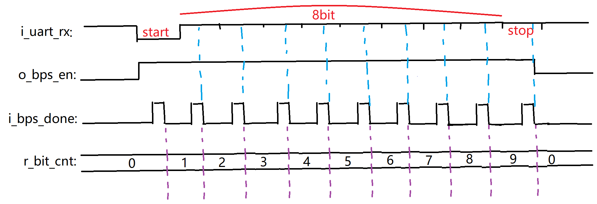
串口数据串并转换模块时序分析:
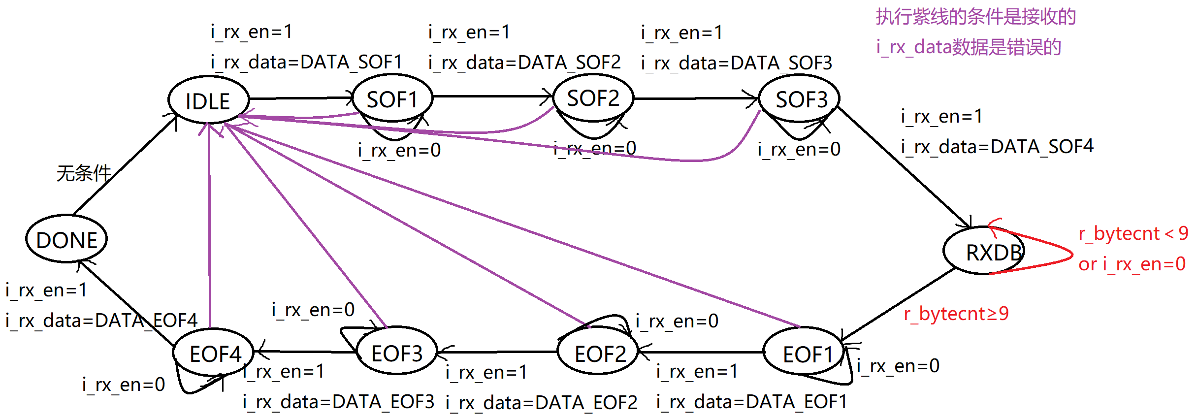
指令译码模块的状态转换图:在状态的迁移过程中做判断
2.源代码
- 顶层模块:uart_decoder_design.v
1 | module uart_decoder_design( |
- 子模块:bps_design.v
1 | module bps_design#( |
- 子模块:s2p_design.v
1 | //串并转化模块 |
- 子模块:beep_design.v
1 | module beep_design( |
- 子模块:decoder_design.v
1 | module decoder_design( |
3.Testbench
1 |
|
4.仿真结果
- RTL视图
- 仿真波形